

 Manufacturers
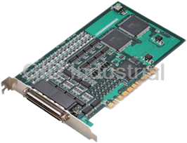
PORTWELL SMC-8DL-PCI
Description
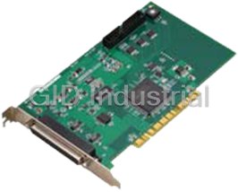
This product is a motion control board for PCI bus conformity that can position of a stepping motor and a servomotor(a pulse line input method). It is equipped with functions such as positioning, origin return, linear interpolation, and a S type accelerate and decelerate. And linear interpolation at multi-axes interval, overwriting of speed and position are possible. It has you use it by a wide use, such as a semiconductor production device, a tester, multi-axes robot or a X-Y robot.
Part Number
SMC-8DL-PCI
Price
Request Quote
Manufacturer
PORTWELL
Lead Time
Request Quote
Category
Contec I/O Products
Specifications
Categorization Information
Contec I/O Products
Features
- A stepping motor or a servomotor of 8 axes can be control easily by software in Windows.
- Control functions are possible, such as positioning, origin return, linear interpolation, and a S type accelerate and decelerate. Capable of controlling the jogging at fixed speed or by linear/S-curve acceleration and deceleration, positioning, and origin returning.
- Capable of using an encoder supporting differential output, TTL level output, open-collector output
- Capable of pulse output of up to 9.8 Mpps. Offering a choice of motor control command pulses selectable from among common, 2, and 90-degree phase-shifted pulses.
- Overriding of Speed and a position are possibility; (speed and an aim position are be changed during movement).
- Comparator circuits allowing the set value and counter value to be compared. A pair of comparator circuits are provided for each axis, allowing the set value and counter value to be compared with each other. They also allow signals to be output while comparator conditions are met. Seven general-purpose inputs are provided for each axis, five of which are also available as alarm, positioning completion, deceleration stop, counter latch, and positioning start inputs. Logic can be changed by software. * This function is supported in driver API-SMC(WDM) Ver.2.00(can download it from the middle of March as plan).
Datasheet

Extracted Text
Ver.1.11 High-speed line driver output 8 axes motion control board for PCI SMC-8DL-PCI This product is a PCI bus-standard motion control board that can position a stepping motor or (a pulse-train input type of) servomotor. This product has the functions for positioning, origin return, linear interpolation, and for S-curve acceleration and deceleration, capable of multi-axial linear interpolation and speed/position overriding. This product covers a wide range of applications including semiconductor equipment, test instruments, multi-axis robots, and X-Y robots. This product can control up to eight axes alone. Using the bundled driver library [API-PAC(W32)], you can create Windows application software for this board in your favorite programming language supporting Win32 API functions, such as Visual Basic or Visual C++. * Specifications, color and design of the products are subject to About Migration From The Existing Products change without notice. This product cannot use [API-SMC(98/PC)] (CD-ROM attached) which is the driver software for the existing products SMC-2P(PCI), SMC-4P(PCI), and SMC-3(PC). [API-SMC(98/PC)] (bundled CD-ROM) cannot be used. Please use [API-SMC(WDM)] (bundled CD-ROM) which is the driver software for this product. As a reference material when migrating from the existing products to this product, “Migration guide” which summarizes migration methods and differences about initial settings and API function units is provided. Please use the guide for your reference. ”Migration guide” can be downloaded from the download library of CONTEC’s Web site (http://www.contec.com/download) Features Capable of multi-axis independent control and pulse Comparator circuits allowing the set value and counter output up to 9.8Mpps value to be compared Control for up to 8 axes and motor control pulse output up to A pair of comparator circuits is provided for each axis, allowing 9.8Mpps are available. the set value and counter value to be compared with each other. Command pulse for motor control supports common pulse, They also allow signals to be output while comparator independent pulse and 90° phase difference pulse. conditions are met. Limit input 3channels/axis, general-purpose input Provided with seven general-purpose input pins and three 7channels/axis, and general-purpose output 3channels/axis general-purpose output pins per axis are equipped. Also, depending on the software setting, 5 Seven general-purpose inputs are provided for each axis, five general-purpose inputs can be used as alarm inputs, and of which are also available as alarm, positioning completion, general-purpose outputs as deviation counter clear outputs. deceleration stop, counter latch, and positioning start inputs. Capable of controlling the jogging at fixed speed or by Logic can be changed by software. linear/S-curve acceleration and deceleration, positioning, Three output pins are provided for each axis. The output and origin returning signals can be switched among alarm clear output, driver Carrying a motor control IC in the PCL6100 series from Nippon deviation clear output and comparator output by the software. Pulse Motor Co., Ltd., capable of controlling jogging, Logic can be changed by software. positioning, origin returning, synchronization control and linear Dedicated terminal strip CCB-SMC2 (option) available interpolation focusing on the ease of use for wiring Provided with various input/output formats enabling A dedicated terminal strip CCB-SMC2 (option) which assigns connection to an encoder input circuit as well as pulse signals for each axis is provided. Driver units and limit output circuit. sensors for stepping motors and servo motors can be Encoder input circuits can be connected with differential output, connected up to 4 pieces. TTL level output, and open-collector output. Pulse output circuits can be connected with differential input, opto-coupler and TTL level input. With the multi-axis synchronization control function, capable of aligning the timing for operation start and end Synchronization control of multi-axis simultaneous start/stop control, linear interpolation operation is available. Capable of speed and position overriding Capable of changing the speed and target position during operation SMC-8DL-PCI 1 Ver.1.11 Pulse Output Section Specification Item Specification Pulse rate 0.3 - 9.8 Mpps Common Section Output signal name CW : pulse / CW output Item Specification CCW : direction / CCW output Output signal system 2 Pulse types (pulse for positive/negative direction) or the Control target Stepping motor or servo motor driver unit(pulse train input type) common pulse type (pulse signal/directional signal), Number of axes to control 8 axes 90-degree phase difference pulse (lead/lag pulse) Device used PCL6143 (Nippon Pulse Motor CO., LTD.) or equivalence to it Output form Un-isolated differential line driver output Interrupt 1 ch Device used AM26LS31(T.I) or equivalence to it Interrupt factor At the time of stop by positive-direction end limit input ON H-level output voltage 2.5V - 5.25V At the time of stop by negative-direction end limit input ON L-level output voltage 0V - 0.5V At the time of stop by alarm input on At the time of stop by simultaneous stop operation Output rating current (Max.) 20mA At the time of stop by deceleration (decelerated stop) input on At the time of occurring the encoder input error General-purpose Output Section The other event (setting by the software) Item Specification I/O address Any 128 ports boundary Number of signal channel 3ch/axis Current consumption 5VDC 1200mA Output signal name OUT1 : general-purpose output (Max.) OUT2 : general-purpose output Operating condition 0 - 50°C, 10 - 90% (No condensation) OUT3 : general-purpose output PCI bus specification 32-bit, 33MHz, Universal key shapes supported *1 (Each output pin can be switched with the following functions) Dimension (mm) 176.41(L) x 106.68(H) ALMCLR : alarm clear output Connector used HDRA-E100W1LFDT1EC-SL+ ERC : driver differential clear output [made by HONDA TSUSHIN KOGYO CO., LTD.] or equivalence CP1 : comparator1 output to it CP2 : comparator2 output Weight 120g Signal specification Un-isolated open collector output (current sink type) *1 This board requires power supply at +5 V from an expansion slot (it does not work on a (Enables selecting the positive/negative logic by using the machine with a +3.3V power supply alone). Software) Response time (Max.) 10 μsec (when using the loading on the input side 510Ω, Encoder Input Section +24VDC) Item Specification Rated output current (Max.) 100mA per 1ch, 300mA per 1axis Encode type Incremental Rated output withstanding 50VDC Maximum counter value 8000000h - 7FFFFFFh(-134,217,728 - 134,217,727), 28 bit voltage (Max.) Input signal type Single-phase input (UP/DOWN/Z) / Phase input(A/B/Z) Supported output type Differential output, TTL level output, open-collector output Device used AM26LS32A(T.I) or equivalence to it Support Software Terminal resister 150Ω (Separable with SW) Receiver input sensitivity ±200mV Windows version of motion control driver API-SMC(WDM) In-phase input voltage ±7V range [Stored on the bundled CD-ROM driver library 10m (Depending on the time of connecting the differential output, API-PAC(W32)] wiring environment and input frequency) Distance in which signal 3m (Depending on the time of connecting the open-collector The API-SMC(WDM) is the Windows version driver library can be extended output, wiring environment and input frequency) software that provides products in the form of Win32 API 1.5m (Depending on the time of connecting the TTL level output, functions (DLL). Various sample programs such as Visual wiring environment and input frequency) 5MHz (Depending on the time of connecting the differential Basic and Visual C++, etc and diagnostic program useful for output, two-phase input, multiply by 4, duty 50%), checking operation is provided. 3MHz (Depending on the time of connecting the TTL level output, Response frequency two-phase input, multiply by 4, duty 50%), < Operating environment > 1MHz (Depending on the time of connecting the open-collector OS Windows 7, Vista, XP, Server 2008, output, two-phase input, multiply by 4, duty 50%) Server 2003, 2000 Limit Input Section Adaptation language Visual Basic, Visual C++, Visual C# Item Specification You can download the updated version from the CONTEC’s Signal channel 3ch/axis (original point, Forward limit, reserve limit) Web site (http://www.contec.com/apipac/). For more details Input signal name ORG : origin input on the supported OS, applicable language and new information, +LIM : positive direction end limit input please visit the CONTEC’s Web site. -LIM : negative direction end limit input Input logic Enables selecting the positive/negative logic by using the Software Cable & Connector Input type Opto-isolated input (corresponding to current sink output) Response time (Max.) 200 μsec Input resister 4.7kΩ Cable (Option) Input ON current 2.0mA or more Shielded Cable With Two 100pin Connector Input OFF current 0.16mA or less : PCB100PS-0.5 (0.5m) External circuit power supply 12V - 24VDC(±10%) : PCB100PS-1.5 (1.5m) General-purpose Input Section : PCB100PS-3 (3m) Item Specification : PCB100PS-5 (5m) Signal channel 7ch/axis Flat Cable with One 100-Pin Connector Input signal name IN1/ALM : alarm input, general-purpose input IN2/INP : positioning completion input, general-purpose input : PCA100P-1.5 (1.5m) IN3/SD : deceleration (decelerated stop) input, general-purpose : PCA100P-3 (3m) input : PCA100P-5 (5m) IN4/LTC : counter latch input, general-purpose input IN5/PCS : positioning control start input, general-purpose input IN6 : general-purpose input IN7 : general-purpose input Input logic Enables selecting the positive/negative logic by using the Software Input type Opto-coupler input (corresponding to current sink output) Response time (Max.) 200 μsec Input resister 4.7kΩ Input ON current 2.0mA or more Input OFF current 0.16mA or less External circuit power 12V - 24VDC(±10%) supply SMC-8DL-PCI 2 Ver.1.11 How to connect the connectors Accessories The on-board interface connector (CAN, CNB) is used when Accessories (Option) connecting this product and the external devices. Connection Conversion Board for SMC : CCB-SMC2 *1*2*3 Interface connector Screw Terminal (M3*100) : EPD-100A *2*3*4 *1 Distributes 100-pin 0.8-mm pitch connector x 1 to: D-SUB 37 connector x 4, D-SUB-9 CNB CNA connector x 4. *2 A PCB100PS optional cable is required separately. - Connector used HDRA-E100W1LFDT1EC-SL+ *3 Cables and accessories are required each connector. [mfd.by HONDA TSUSHIN *4 “Spring-up” type terminal is used to prevent terminal screws from falling off. KOGYO CO., LTD] equivalent * Check the CONTEC’s Web site for more information on these options. - Compatible connector HDRA-E100MA1[mfd.by HONDA TSUSHIN Packing List KOGYO CO., LTD] Board [SMC-8DL-PCI] …1 * Please refer to page 2 for more information on the supported cable and accessories. First step guide …1 Pin Assignments of Interface Connector (CNA, CNB) *1 The CD-ROM contains the driver software and User’s Guide. CNB 100 axis0 : P-COM 50 axis2 : P-COM Block Diagram axis0 : IN1/ALM 99 49 axis2 : IN1/ALM axis0 : IN2/INP 98 48 axis2 : IN2/INP axis0 : IN3/SD 97 47 axis2 : IN3/SD axis0 : IN4/LTC 96 46 axis2 : IN4/LTC axis0 : IN5/PCS 95 45 axis2 : IN5/PCS axis0 : IN6 94 44 axis2 : IN6 Driver Pulse output axis0 : IN7 93 43 axis2 : IN7 Axis0 axis0 : ORG 92 42 axis2 : ORG Receiver Encoder input axis0 : +LIM 91 41 axis2 : +LIM axis0 : -LIM 90 Photo-coupler Limit input 40 axis2 : -LIM axis1 : P-COM 89 39 axis3 : P-COM - - - axis1 : IN1/ALM 88 38 axis3 : IN1/ALM Motor controller - - - axis1 : IN2/INP 87 37 axis3 : IN2/INP PCL6143 - - - axis1 : IN3/SD 86 36 axis3 : IN3/SD - - - axis1 : IN4/LTC 85 35 axis3 : IN4/LTC axis1 : IN5/PCS 84 Driver Pulse output 34 axis3 : IN5/PCS axis1 : IN6 83 33 axis3 : IN6 axis1 : IN7 82 Receiver Encoder input Axis3 32 axis3 : IN7 axis1 : ORG 81 31 axis3 : ORG Photo-coupler Limit input axis1 : +LIM 80 30 axis3 : +LIM axis1 : -LIM 79 29 axis3 : -LIM axis0 : A+ 78 28 axis2 : A+ axis0 : A- 77 27 axis2 : A- axis0 : B+ 76 axis2 : B+ 26 axis0 : B- 75 25 axis2 : B- Control circuit Driver Pulse output axis0 : Z+ 74 axis2 : Z+ 24 FPGA axis0 : Z- 73 23 axis2 : Z- Axis4 Receiver Encoder input axis1 : A+ 72 axis3 : A+ 22 axis1 : A- 71 21 axis3 : A- Photo-coupler Limit input axis1 : B+ 70 axis3 : B+ 20 axis1 : B- 69 19 axis3 : B- - - axis1 : Z+ 68 18 axis3 : Z+ Motor controller - - axis1 : Z- 67 17 axis3 : Z- PCL6143 - - axis0 : OUT3 66 16 axis2 : OUT3 - - axis0 : OUT2 65 15 axis2 : OUT2 Driver Pulse output axis0 : OUT1 64 14 axis2 : OUT1 axis0 : DIR+/CCW+ 63 13 axis2 : DIR+/CCW+ Receiver Encoder input Axis7 axis0 : DIR-/CCW- 62 12 axis2 : DIR-/CCW- axis0 : OUT+/CW+ 61 11 axis2 : OUT+/CW+ Photo-coupler Limit input axis0 : OUT-/CW- 60 10 axis2 : OUT-/CW- GND 59 9 GND axis1 : OUT3 58 8 axis3 : OUT3 * Only SMC-8DL-PCI axis1 : OUT2 57 7 axis3 : OUT2 axis1 : OUT1 56 6 axis3 : OUT1 General-purpose axis1 : DIR+/CCW+ 55 Transistor 5 axis3 : DIR+/CCW+ output axis1 : DIR-/CCW- 54 4 axis3 : DIR-/CCW- (Each axis 3ch) axis1 : OUT+/CW+ 53 3 axis3 : OUT+/CW+ General-purpose Photo-coupler axis1 : OUT-/CW- 52 2 axis3 : OUT-/CW- input SMC-4DL-PCI GND 51 1 GND (Each axis 7ch) SMC-8DL-PCI * Axis0 - Axis3 of this manual corresponds to Axis No.1 - Axis No.4 in API-SMC(WDM). P-COM Plus common B+ Encoder phase B input+ General-purpose input1/Alarm IN1/ALM B- Encoder phase B input- input General-purpose input2/Positionig IN2/INP Z+ Encoder phase Z input+ input General-purpose input3/Slow IN3/SD Z- Encoder phase Z input- down input General-purpose input4/counter IN4/LTC OUT1 General-purpose output1 latch input General-purpose IN5/PCS input5/positioning operation start OUT2 General-purpose output2 input IN6 General-purpose input6 OUT3 General-purpose output3 IN7 General-purpose input7 DIR+/CCW+ Direction/CCW output+ ORG Origin input DIR-/CCW- Direction/CCW output- +LIM Positive-direction limit OUT+/CW+ Pulse/CW output+ -LIM Negative-direction limit OUT-/CW- Pulse/CW output- Power ground input (common to A+ Encoder phase A input+ GND internal GND) A- Encoder phase A input- SMC-8DL-PCI 3 PCI Bus* Ver.1.11 Connection with the opto-coupler input (When the driver CNA unit guarantees the connection with the differential output) GND 1 51 GND Driver Unit Board axis7 : OUT-/CW- 2 52 axis5 : OUT-/CW- axis7 : OUT+/CW+ 3 53 axis5 : OUT+/CW+ axis7 : DIR-/CCW- 4 AM26LS31 or equivalence to it 54 axis5 : DIR-/CCW- CW+ axis7 : DIR+/CCW+ 5 55 axis5 : DIR+/CCW+ CW axis7 : OUT1 6 56 axis5 : OUT1 CW axis7 : OUT2 7 57 axis5 : OUT2 CW- axis7 : OUT3 8 58 axis5 : OUT3 GND 9 59 GND axis6 : OUT-/CW- 10 60 axis4 : OUT-/CW- CCW+ axis6 : OUT+/CW+ 11 61 axis4 : OUT+/CW+ CCW CCW axis6 : DIR-/CCW- 12 62 axis4 : DIR-/CCW- axis6 : DIR+/CCW+ 13 63 axis4 : DIR+/CCW+ CCW- axis6 : OUT1 14 64 axis4 : OUT1 axis6 : OUT2 15 65 axis4 : OUT2 axis6 : OUT3 16 66 axis4 : OUT3 axis7 : Z- 17 67 axis5 : Z- axis7 : Z+ 18 68 axis5 : Z+ Connection with the opto-coupler input axis7 : B- 19 69 axis5 : B- Driver Unit axis7 : B+ 20 70 axis5 : B+ Board axis7 : A- 21 71 axis5 : A- axis7 : A+ 22 72 axis5 : A+ AM26LS31 or equivalence to it CW+ axis6 : Z- 23 73 axis4 : Z- CW axis6 : Z+ 24 74 axis4 : Z+ CW axis6 : B- 25 75 axis4 : B- CW- axis6 : B+ 26 76 axis4 : B+ axis6 : A- 27 77 axis4 : A- axis6 : A+ 28 78 axis4 : A+ CCW+ axis7 : -LIM 29 79 axis5 : -LIM CCW CCW axis7 : +LIM 30 80 axis5 : +LIM axis7 : ORG 31 81 axis5 : ORG CCW- axis7 : IN7 32 82 axis5 : IN7 axis7 : IN6 33 83 axis5 : IN6 GND axis7 : IN5/PCS 34 84 axis5 : IN5/PCS axis7 : IN4/LTC 35 85 axis5 : IN4/LTC axis7 : IN3/SD 36 86 axis5 : IN3/SD axis7 : IN2/INP 37 87 axis5 : IN2/INP axis7 : IN1/ALM 38 88 axis5 : IN1/ALM Connection with TTL level input axis7 : P-COM 39 89 axis5 : P-COM axis6 : -LIM 40 90 axis4 : -LIM Driver Unit Board axis6 : +LIM 41 91 axis4 : +LIM axis6 : ORG 42 92 axis4 : ORG AM26LS31 or equivalence to it Vcc Vcc axis6 : IN7 43 93 axis4 : IN7 axis6 : IN6 44 94 axis4 : IN6 CW+ CW axis6 : IN5/PCS 45 95 axis4 : IN5/PCS CW axis6 : IN4/LTC 46 96 axis4 : IN4/LTC axis6 : IN3/SD 47 97 axis4 : IN3/SD CW- axis6 : IN2/INP 48 98 axis4 : IN2/INP axis6 : IN1/ALM 49 99 axis4 : IN1/ALM Vcc axis6 : P-COM 50 100 axis4 : P-COM Vcc CCW+ CCW * Axis4 - Axis7 of this manual corresponds to Axis No.5 - Axis No.8 in API-SMC(WDM). CCW P-COM Plus common B+ Encoder phase B input+ CCW- General-purpose input1/Alarm IN1/ALM B- Encoder phase B input- input GND General-purpose input2/Positionig IN2/INP Z+ Encoder phase Z input+ input General-purpose input3/Slow IN3/SD Z- Encoder phase Z input- down input CAUTION General-purpose input4/counter IN4/LTC OUT1 General-purpose output1 The pulse output part of this product outputs the voltage by latch input General-purpose 2.5V or more at the High level output, and outputs the IN5/PCS input5/positioning operation start OUT2 General-purpose output2 voltage of 0.5V or less at the Low level output. When input IN6 General-purpose input6 OUT3 General-purpose output3 connecting with the photo-coupler input or the TTL level input, IN7 General-purpose input7 DIR+/CCW+ Direction/CCW output+ please connect it after confirming the specification in the ORG Origin input DIR-/CCW- Direction/CCW output- pulse input part of the driver unit operates by the +LIM Positive-direction limit OUT+/CW+Pulse/CW output+ -LIM Negative-direction limit OUT-/CW- Pulse/CW output- above-mentioned voltage. In addition, please insert a Power ground input (common to current-limiting resistor according to the allowable current A+ Encoder phase A input+ GND internal GND) and drive current of the connected input circuit. A- Encoder phase A input- To prevent the circuit from malfunctioning due to noise, wire Connecting Output Signals it as far away from other signal lines and noise sources as possible. Pulse output circuit (CW, CCW) Pulse output circuit on this product is illustrated below. The signal output is a differential line-driver output. Connection with the differential input CAUTION Please use the twisted-pair cable that does the shield processing as a noise measures when connecting it with the differential input. SMC-8DL-PCI 4 Ver.1.11 Connection with the TTL level output Control signal/general-purpose signal output circuit Board Driver Unit (OUT1 - OUT3, ERC, CP1, CP2) Vcc Vcc Vcc Output circuit of each output signal on this product is illustrated TTL level AM26LS32A or below. The signal output is an open-collector output. A output equivalence to it A+ Phase A+ ground wire must therefore be connected for driving. Board Driver Unit A- OUT1 - OUT3 Vcc Vcc Vcc TTL level AM26LS32A or output equivalence to it B+ Phase B+ GND - + +12 - +24VDC B- Vcc Vcc Vcc TTL level AM26LS32A or output equivalence to it Z+ Phase Z+ Connecting Input Signals Encoder input circuit Encoder input circuit on this product is illustrated below. The Z- GND GND signal input is a differential input capable of connecting a line driver output, TTL level output and open-collector output. Connection with the differential output Board Driver Unit CAUTION Vcc When connecting TTL level output signals, please do not Vcc insert a terminating resistor with reference to "Setting the AM26LS32A or equivalence to it A+ Phase A+ Terminating Resistor in chapter 2". When inserted with a terminating resistor (factory setting), this product may malfunction, overheat, or causes a failure. Restrict the use of cables to 1.5m for the TTL level output. A- Phase A- To prevent the circuit from malfunctioning due to noise, wire it as far away from other signal lines and noise sources as Vcc Vcc possible. AM26LS32A or equivalence to it B+ Phase B+ Phase B- B- Vcc Vcc AM26LS32A or equivalence to it Z+ Phase Z+ Phase Z- Z- GND GND Connector Shell CAUTION Please use the twisted-pair cable that does the shield processing as a noise measures when connecting it with the differential output. Restrict the use of cables to 10m for the line driver output. SMC-8DL-PCI 5 Ver.1.11 Connection with the open-collector output Connection Connection Examples Examples Given below are practical examples of connection of this product that outputs pulses by the independent pulsing method to motor drivers. These examples show the connections through axis0 (Axis No.1 in API-SMC(WDM)). Example of Connection to driver unit (Σ II Series) for Servo motor CAUTION When connecting open-collector output signals, please do not insert a terminating resistor with reference to "Setting the Terminating Resistor in chapter 2". When inserted with a terminating resistor (factory setting), this product may malfunction, overheat, or causes a failure. Restrict the use of cables to 3m for the open-collector output. To prevent the circuit from malfunctioning due to noise, wire it as far away from other signal lines and noise sources as possible. * Please connect the Shield Line of cable with the Connector Shell. Limit input/general-purpose input/control input circuit (IN1 - IN7, +LIM, -LIM, ORG) Motion control system configuration The limit input/general-purpose input/control input circuit on Stepping motor Servo motor Limit sensor this board is illustrated below. The signal input is an opto-isolated, current driven input (sink type). To drive the limit input/general-purpose input/control input block, therefore, an external power supply is required at +12 - +24 V External Board Device Vcc Driver unit Conversion cable CCB-SMC2 PCB-100PS External Plus SMC-4DL-PCI Power Supply Common SMC-8DL-PCI +12 - +24VDC +12V - Input +24VDC Swich Photocoupler Pin DC Power Supply Vcc Component features Item Description SMC-8DL-PCI When installed on the PC, this board generates pulses required for (Main board) position control. PCB-100PS (Option) This cable connects the board to the CCB-SMC2. This screw terminal is used to efficiently connect the devices (the Input board, driver unit, DC power supply, limit sensor) required for Swich CCB-SMC2 (Option) Photocoupler Pin position control. The screw terminal can connect a four-axes motion control system alone. The shape of the control connector of each driver unit is largely different depending on the manufacturer and type. A conversion Conversion cable (User) cable must be prepared to connect each driver unit to the CCB-SMC2. Driver unit (Motor maker) Motor and driver unit to be subject to motion control. * Input pin is IN1 - IN7, +LIM, -LIM, ORG. Available in various types by motor capacity, power-supply voltage, Stepping motor Servo and motor shape. Select the ones that best fit your needs. motor(Motor maker) This sensor is installed at the forward/backward limit and origin Limit sensor (Switch detection positions. When a table is used in the system, the maker) sensor is bundled with the table. For a self-made system, use commercially available switches. DC Power supply Power supply to the CCB-SMC2. Use a 12 - 24-VDC power (Power supply maker) supply. SMC-8DL-PCI 6
Frequently asked questions
Why choose IPC Station?

What is IPC Station' warranty policy for the SMC-8DL-PCI?
What carriers does IPC Station use to ship parts?
Does IPC Station sell to international (non-USA) customers?
What methods of payment does IPC Station accept?
Why buy from GID?

Quality
We are industry veterans who take pride in our work

Protection
Avoid the dangers of risky trading in the gray market

Access
Our network of suppliers is ready and at your disposal

Savings
Maintain legacy systems to prevent costly downtime

Speed
Time is of the essence, and we are respectful of yours
Related Products
This product is a PCI bus compatible interface board with high-precision analog input(16-bit,8 ch) a...
Unisolated Analog Input Board for PCI
It is an analog input terminal for USB2.0 that an analog measurement is possible by being connected ...
This product is a USB2.0-compliant analog I/O unit that extends the analog I/O function of USB port ...
12-bits Analog I/O Board(Low Gain) for PCI
This product is a USB2.0-compliant analog I/O unit that extends the analog I/O function of USB port ...
Request a Quote

The quote request has been received
Close

Facing challenges or have inquiries? Feel free to contact us!
Call Us +1-469-283-2440
What they say about us
FANTASTIC RESOURCE
One of our top priorities is maintaining our business with precision, and we are constantly looking for affiliates that can help us achieve our goal. With the aid of GID Industrial, our obsolete product management has never been more efficient. They have been a great resource to our company, and have quickly become a go-to supplier on our list!
Bucher Emhart Glass
EXCELLENT SERVICE
With our strict fundamentals and high expectations, we were surprised when we came across GID Industrial and their competitive pricing. When we approached them with our issue, they were incredibly confident in being able to provide us with a seamless solution at the best price for us. GID Industrial quickly understood our needs and provided us with excellent service, as well as fully tested product to ensure what we received would be the right fit for our company.
Fuji
HARD TO FIND A BETTER PROVIDER
Our company provides services to aid in the manufacture of technological products, such as semiconductors and flat panel displays, and often searching for distributors of obsolete product we require can waste time and money. Finding GID Industrial proved to be a great asset to our company, with cost effective solutions and superior knowledge on all of their materials, it’d be hard to find a better provider of obsolete or hard to find products.
Applied Materials
CONSISTENTLY DELIVERS QUALITY SOLUTIONS
Over the years, the equipment used in our company becomes discontinued, but they’re still of great use to us and our customers. Once these products are no longer available through the manufacturer, finding a reliable, quick supplier is a necessity, and luckily for us, GID Industrial has provided the most trustworthy, quality solutions to our obsolete component needs.
Nidec Vamco
TERRIFIC RESOURCE
This company has been a terrific help to us (I work for Trican Well Service) in sourcing the Micron Ram Memory we needed for our Siemens computers. Great service! And great pricing! I know when the product is shipping and when it will arrive, all the way through the ordering process.
Trican Well Service
GO TO SOURCE
When I can't find an obsolete part, I first call GID and they'll come up with my parts every time. Great customer service and follow up as well. Scott emails me from time to time to touch base and see if we're having trouble finding something.....which is often with our 25 yr old equipment.
ConAgra Foods