

 Manufacturers
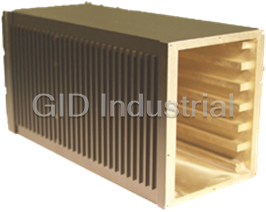
PIXUS VME64X BACKPLANES
Description
None available.
Part Number
VME64X BACKPLANES
Price
Request Quote
Manufacturer
PIXUS
Lead Time
Request Quote
Category
Uncategorized
Specifications
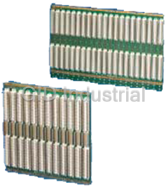
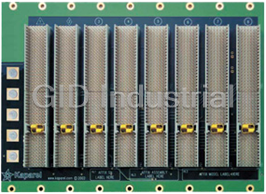
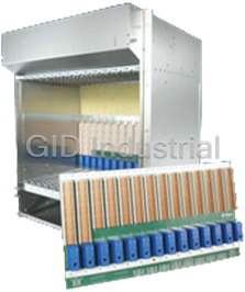
Pixus Backplanes Division offers VME64x backplanes in 6U and 6.5U heights.The 6.5U size allows extra space at the bottom of the backplane for extra power taps. Pixus also offers 9U versions with 47-pin power connectors for use in low-profile horizontal enclosures.
Description
5, 7, 9, 10, 12, 21 slots
Slots
Features
- High-speed backplane
- Conforms to ANSI/VITA 1.1 and IEEE 1101
- Automatic daisy chaining
- Optionally available with or without PO connector
Datasheet

Extracted Text
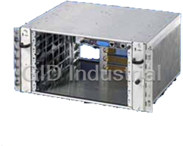
Section 3_104-155 4/7/04 8:47 AM Page 24 Order Information ■ Backplanes VME64x Technical Specifications: Number of layers 10 Layer structure Optimized for best RF protection. Outer layers designed as shielding surface PCB thickness 4.3 mm Ohmic resistance of signal lines < 1.5 Ohm Surge impedance Z of signal lines 50 Ohm Basic current consumption with active: <0.1 A termination on two sides Power supply: - Busbar with M6 screw terminal x - M4 screw terminal and Faston 6.3 x 0.8 mm x - < 5 slots FASTON .3 x 0.8 mm Current carrying capacity of busbar 200 A Current carrying capacity of a combined 25 A double flat-pin connector/screw terminal Current carrying capacity of a 10 A FASTON flat-pin connector Current carrying capacity of the assembly, +3.3 V 12.5 A per slot +12 V 9.0 A -12 V 1.5 A +5 VSTDBY 1.5 A +48 V (35-75 V) 3.0 A Termination of ON/IN board active Installation height 6U/6.5U Distance between slots 4HP Connector Press-fit system, quality category 2, 400 connection cycles 160 pins compatible with c96 J0 optional distance 2 mm, 95/133 pins Operating temperature range Active termination 0°…+70°C Passive termination -40°…+85°C Relative humidity 90%, non-condensing Material: Glass epoxy to DIN 40 802 (type FR4) Supply Includes: 1 backplane, fully populated VME64x 6U Slot Dimensions Order No. Order No. (H x W) mm without PO connector with PO connector 5 261.6 x 100 3687608 3687609 7 261.6 x 161.5 3687610 3687611 9 261.6 x 181.5 9904930 9904932 10 261.6 x 202 9904931 9904933 12 261.6 x 242.5 3686634 3686473 21 261.6 x 425.5 3686635 3686474 VME64x 6.5U Slot Dimensions Order No. Order No. (H x W) mm without PO connector with PO connector 5 283.7 x 100 9910012 9910007 7 283.7 x 161.5 9910013 9910008 9 283.7 x 181.5 9910014 9910009 10 283.7 x 202 9904928 9904929 12 283.7 x 242.5 9910015 9910010 21 283.7 x 425.5 9910016 9910011 Accessories for mounting of the backplanes, see page 122-123 127 Section 3_104-155 4/7/04 8:47 AM Page 25 Backplanes For VME ■ System Bus VME64x System Bus VME J1/J2 Monolithic Order No. see page 127. Order No. see page 130. Applications Areas Applications Areas Installation in VME computer systems for power and signal distribution, Installation in VME computer systems for power and signal distribution, for plug-in boards and assemblies for for plug-in boards and assemblies for ■ Medical ■ Process control ■ Process control ■ Traffic guidance systems ■ Traffic guidance systems ■ Image processing ■ Image processing ■ Automation ■ Automation ■ Medical ■ Military ■ Military Especially suitable for data transfer using fast drivers Design Features Design Features ■ High-speed VME system bus ■ High-speed VME system bus ■ Optical fiber epoxide to DIN 40 802 (type FR4) ■ Optical fiber epoxide to DIN 40 802 (type FR4) ■ 6U with 32-bit data width ■ 6U and 6.5U with 64-bit data width ■ 2 - 21 slots ■ 5, 7, 9, 10, 12, 21 slots ■ Automatic daisy chaining ■ Automatic daisy chaining ■ 6 layer multilayer ■ 10 layer multilayer ■ Termination of ON/IN Board passive or active ■ With or without PO connector User Benefits User Benefits ■ High-speed backplane ■ High-speed backplane ■ Conforms to ANSI/VITA 1.1 and IEEE 1101 ■ Conforms to ANSI/VITA 1.1 and IEEE 1101 ■ Automatic daisy chaining ■ Automatic daisy chaining ■ Passive or active termination ■ Optionally available with or without PO connector 128 Section 3_104-155 4/7/04 8:47 AM Page 21 Technical Specification ■ VMEbus n General Technical Data For The VMEbus The VMEbus, based on standard 1-1994, and supports 64-bit data backward-compatible, so that Consistent shielding of every signal IEEE 1014 and IEC 821, has traffic. VME64x is an addition to the assemblies with 96-pin connectors trace ensures minimum coupling and become established worldwide VME family according to ANSI/VITA to DIN 41612 can still be used. All therefore guarantees problem-free as an industry standard. 1.1-1997 and is available with an Kaparel/Rittal VMEbus boards are of operation, even with an expansion to optional 133-pin, 2 mm J0 a HIGHSPEED DESIGN. Minimum 64-bit mode with the 2e protocol The VME64 is an extension to the connector. 160-pin connectors are reflections are achieved, due to even (160Mbyte/s). VME family according to ANSI/VITA used for VME64x. This system remains surge impedance on the signal track. Daisy Chain Connection Termination In order to avoid malfunctions on signal tracks caused by reflections at the For daisy chain connections, a distinction is made between manual daisy open track end, these must be terminated with the VMEbus. Termination may chaining and automatic daisy chaining. Automatic daisy chaining eliminates be either at the ON/IN board (on the backplane) or the OFF board (external). the need for jumper connection, and time-consuming insertion and extraction There are two types of termination - passive and active. The advantage of are eliminated. Furthermore, possible mis-connections are avoided. active termination lies in its lower closed-circuit current consumption, whilst Automatic daisy chaining can be achieved in two ways. Kaparel/Rittal passive termination is distinguished by a superior frequency response and a VMEbuses are generally supplied with automatic daisy chaining. wider temperature range. Pin assignment J1 Pin assignment J2 Pin assignment for J1 connector, VME64x Pin assignment for J2 connector, VME64x Pin assignment for J1 connector,VME Pin assignment for J2 connector,VME Pin No. Row z Row a Row b Row c Row d Pin No. Row z Row a Row b Row c Row d 1 MPR D00 BBSY D08 VPC 1UD User def. + 5 V User def. UD 2 GND D01 BCLR D09 GND 2 GND User def. GND User def. UD 3MCLK D02 ACFAIL D10 +V1 3UD User def. Retry User def. UD 4 GND D03 BG0IN D11 +V2 4 GND User def. A24 User def. UD 5 MSD D04 BG0OUT D12 RSVU 5UD User def. A25 User def. UD 6 GND D05 BG1IN D13 -V1 6 GND User def. A26 User def. UD 7 MMD D06 BG1OUT D14 -V2 7UD User def. A27 User def. UD 8 GND D07 BG2IN D15 RSVU 8 GND User def. A28 User def. UD 9 MCTL GND BG2OUT GND GAP 9UD User def. A29 User def. UD 10 GND SYSCLK BG3IN SYSFAIL GAO 10 GND User def. A30 User def. UD 11 RTRY1 GND BG3OUT BERR GA1 11 UD User def. A31 User def. UD 12 GND DS1 BR0 SYSRESET +3.3 V 12 GND User def. GND User def. UD 13 RSVBUS DS0 BR1 LWORD GA2 13 UD User def. + 5 V User def. UD 14 GND WRITE BR2 AM5 +3.3 V 14 GND User def. D16 User def. UD 15 RSVBUS GND BR3 A23 GA3 15 UD User def. D17 User def. UD 16 GND DTACK AM0 A22 + 3.3 V 16 GND User def. D18 User def. UD 17 RSVBUS GND AM1 A21 GA4 17 UD User def. D19 User def. UD 18 GND AS AM2 A20 + 3.3 V 18 GND User def. D20 User def. UD 19 RSVBUS GND AM3 A19 RSVBUS 19 UD User def. D21 User def. UD 20 GND IACK GND A18 + 3.3 V 20 GND User def. D22 User def. UD 21 RSVBUS IACKIN SERCLK(1) A17 RSVBUS 21 UD User def. D23 User def. UD 22 GND IACKOUT SERDAT(1) A16 + 3.3 V 22 GND User def. GND User def. UD 23 RSVBUS AM4 GND A15 RSVBUS 23 UD User def. D24 User def. UD 24 GND A07 IRQ7 A14 + 3.3 V 24 GND User def. D25 User def. UD 25 RSVBUS A06 IRQ6 A13 RSVBUS 25 UD User def. D26 User def. UD 26 GND A05 IRQ5 A12 + 3.3 V 26 GND User def. D27 User def. UD 27 RSVBUS A04 IRQ4 A11 LI/I 27 UD User def. D28 User def. UD 28 GND A03 IRQ3 A10 + 3.3 V 28 GND User def. D29 User def. UD 29 SBB A02 IRQ2 A09 LI/O 29 UD User def. D30 User def. UD 30 GND A01 IRQ1 A08 + 3.3 V 30 GND User def. D31 User def. UD 31 SBA - 12 V +5 V STDBT + 12 V GND 31 UD User def. GND User def. UD 32 GND + 5 V + 5 V + 5 V VPC 32 GND User def. + 5 V User def. UD 124 Section 3_104-155 4/7/04 8:47 AM Page 22 Technical Specification ■ VMEbus ■ Automatic Daisy Chaining J1 And J1/J2 Automatic Daisy Chaining VME64x Due to the use of connectors with integral mechanical In this case, the option for automatic daisy chaining is switches, the contact is automatically opened when achieved due to an “or” logic integrated onto the the daughterboard is inserted, and closed again when backplane. When the daughterboard is extracted, the it is extracted. logic closes the daisy chain. Chassis GND Connection Power Connections A continuous, electrically conductive chassis GND plane is Infeed of the main operating voltage + 5 V/+ 3.3 V and connected to the backplane mounting points on the subrack. GND is achieved via busbars with an M6 screw connection. This facilitates EMC-sealed mounting of the backplane on The auxiliary operating voltages are supplied via the subrack. In the case of VME64x, the subrack and system double-FASTONs with an additional M4 screw terminal. earth are RF-coupled by means of capacitors (10nF, 200 V The arrangement of the feed modules on the backplane on each slot). Static charges are discharged via a resistor ensures optimum power supply to the daughterboards for (≥ 1MΩ). A combined connection component is available for problem-free operation. connecting the enclosure earth (screw M4 and FASTON 2.8 or 6.3 x 0.8 mm). Utility Connector Pin Assignment, 7 Pins Pin Assignment, 10/14 Pins Special signals to the power supply 1 GND Sense GND 1 2 GND Sense unit and to external LEDs are routed (5 V) 2+ 5 V Sense on a separate connector on the + 5 V 3 4 + 5 V Sense 3 GND backplanes. ACFAIL- 5 6 ACFAIL- 4+ 5 V Depending on the backplane type, a SYSFAIL- 7 8 SYSFAIL- 7-pin, 10-pin or 14-pin connector 5 ACFAIL- with 2.54 mm spacing is provided. SYSRESET- 9 10 SYSRESET- 6 SYSFAIL- + 3.3 V 11 12 + 3.3 V 7 SYSRESET- GND 13 14 GND Sense (3.3 V) 125 Section 3_104-155 4/7/04 8:47 AM Page 23 Technical Specification ■ VMEbus ■ Geographical Address Pin Assignments (VME64x) Slot Number GAP GA4 GA3 GA2 GA1 GA0 Pin J1-D9 Pin J1-D17 Pin J1-D15 Pin J1-D13 Pin J1-D11 Pin J1-D10 1 Open Open Open Open Open GND 2 Open Open Open Open GND Open 3 GND Open Open Open GND GND 4 Open Open Open GND Open Open 5 GND Open Open GND Open GND 6 GND Open Open GND GND Open 7 Open Open Open GND GND GND 8 Open Open GND Open Open Open 9 GND Open GND Open Open GND 10 GND Open GND Open GND Open 11 Open Open GND Open GND GND 12 GND Open GND GND Open Open 13 Open Open GND GND Open GND 14 Open Open GND GND GND Open 15 GND Open GND GND GND GND 16 Open GND Open Open Open Open 17 GND GND Open Open Open GND 18 GND GND Open Open GND Open 19 Open GND Open Open GND GND 20 GND GND Open GND Open Open 21 Open GND Open GND Open GND Pin Assignments J0 PIN Number ROW Z ROW A ROW B ROW C ROW D ROW E ROW F 1 GND User defined User defined User defined User defined User defined GND 2 GND User defined User defined User defined User defined User defined GND 3 GND User defined User defined User defined User defined User defined GND 4 GND User defined User defined User defined User defined User defined GND 5 GND User defined User defined User defined User defined User defined GND 6 GND User defined User defined User defined User defined User defined GND 7 GND User defined User defined User defined User defined User defined GND 8 GND User defined User defined User defined User defined User defined GND 9 GND User defined User defined User defined User defined User defined GND 10 GND User defined User defined User defined User defined User defined GND 11 GND User defined User defined User defined User defined User defined GND 12 GND User defined User defined User defined User defined User defined GND 13 GND User defined User defined User defined User defined User defined GND 14 GND User defined User defined User defined User defined User defined GND 15 GND User defined User defined User defined User defined User defined GND 16 GND User defined User defined User defined User defined User defined GND 17 GND User defined User defined User defined User defined User defined GND 18 GND User defined User defined User defined User defined User defined GND 19 GND User defined User defined User defined User defined User defined GND 126
Frequently asked questions
Why choose IPC Station?

What is IPC Station' warranty policy for the VME64X BACKPLANES?
What carriers does IPC Station use to ship parts?
Does IPC Station sell to international (non-USA) customers?
What methods of payment does IPC Station accept?
Why buy from GID?

Quality
We are industry veterans who take pride in our work

Protection
Avoid the dangers of risky trading in the gray market

Access
Our network of suppliers is ready and at your disposal

Savings
Maintain legacy systems to prevent costly downtime

Speed
Time is of the essence, and we are respectful of yours
Related Products
The Kaparel/Rittal 23000 Series of 3U PXI backplanes are PXI R2.0 and nPICMG 2.8 draft specification...
Due to its compact design, the 5 U shelf version offers optimum application possibilities, e.g. as a...
Due to its compact design, the 5 U shelf version offers optimum application possibilities, e.g. as a...

The Pixus Backplanes Division leverages designs from Kaparel, a leading innovator of AdvancedTCA des...
The 13U ATCA shelf design has over 15,000 global installs. This superior chassis design has been ado...
Request a Quote

The quote request has been received
Close

Facing challenges or have inquiries? Feel free to contact us!
Call Us +1-469-283-2440
What they say about us
FANTASTIC RESOURCE
One of our top priorities is maintaining our business with precision, and we are constantly looking for affiliates that can help us achieve our goal. With the aid of GID Industrial, our obsolete product management has never been more efficient. They have been a great resource to our company, and have quickly become a go-to supplier on our list!
Bucher Emhart Glass
EXCELLENT SERVICE
With our strict fundamentals and high expectations, we were surprised when we came across GID Industrial and their competitive pricing. When we approached them with our issue, they were incredibly confident in being able to provide us with a seamless solution at the best price for us. GID Industrial quickly understood our needs and provided us with excellent service, as well as fully tested product to ensure what we received would be the right fit for our company.
Fuji
HARD TO FIND A BETTER PROVIDER
Our company provides services to aid in the manufacture of technological products, such as semiconductors and flat panel displays, and often searching for distributors of obsolete product we require can waste time and money. Finding GID Industrial proved to be a great asset to our company, with cost effective solutions and superior knowledge on all of their materials, it’d be hard to find a better provider of obsolete or hard to find products.
Applied Materials
CONSISTENTLY DELIVERS QUALITY SOLUTIONS
Over the years, the equipment used in our company becomes discontinued, but they’re still of great use to us and our customers. Once these products are no longer available through the manufacturer, finding a reliable, quick supplier is a necessity, and luckily for us, GID Industrial has provided the most trustworthy, quality solutions to our obsolete component needs.
Nidec Vamco
TERRIFIC RESOURCE
This company has been a terrific help to us (I work for Trican Well Service) in sourcing the Micron Ram Memory we needed for our Siemens computers. Great service! And great pricing! I know when the product is shipping and when it will arrive, all the way through the ordering process.
Trican Well Service
GO TO SOURCE
When I can't find an obsolete part, I first call GID and they'll come up with my parts every time. Great customer service and follow up as well. Scott emails me from time to time to touch base and see if we're having trouble finding something.....which is often with our 25 yr old equipment.
ConAgra Foods