

 Manufacturers
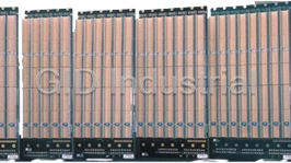
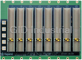
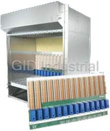
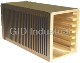
PIXUS PS1400 6U CPCI BACKPLANES
Description
Common 6U CompactPCI backplane sizes include 2, 4, 5, 6, 7, 8 slots. The modular format allows a vast array of configurations and bridgable units to 21 slots.
Part Number
PS1400 6U CPCI BACKPLANES
Price
Request Quote
Manufacturer
PIXUS
Lead Time
Request Quote
Category
Uncategorized
Specifications
Slots
2 to 8, 6U single wide (4HP) cPCI slots
Features
- Any slot count is achieved by connecting backplanes with bridge modules (PS1130)
- 2 to 8, 6U single wide (4HP) cPCI slots / +5 V, 33 MHz PCI bus interface / 32-bit or 64-bit buses available
- User-definable geographic address for each physical slot
- PICMG 2.0 R2.1 CompactPCI and pre-2.1 compatible / PICMG 2.1 R1.0 CompactPCI Hotswap specification compliant
- ATX-compliant power connectors
Datasheet

Extracted Text
Section 2_52-103 4/6/04 4:35 PM Page 22 Ordering CompactPCI Backplanes ■ PS1400 And PS1400B Modular Series For 6U CompactPCI Boards ■ ** PS1400: 8 slot, 6.5U, 64-bit Features: Specifications: **Width throughout modular series is General Description: ■ Any slot count is achieved by 4HP per slot (see configuration chart). Electrical: The PS1400 Series of 6U 64/32-bit connecting backplanes with bridge backplane components allows the PCI Local Bus Specification Rev 2.1 modules (PS1130) construction of CompactPCI systems PICMG 2.0 R2.1 cPCI Specification along the top and bottom edges of the ■ 2 to 8, 6U single wide (4HP) with any number of slots. Each cPCI slots backplanes. Approximately every third PICMG 2.1 R1.0 cPCI Hotswap backplane contains between 2 and 8 mounting hole along the top and ■ +5 V, 33 MHz PCI bus interface Specification slots, and can operate in stand-alone bottom is connected to digital ground. ■ 32-bit or 64-bit busses available mode with a host CPU board and Mechanical: These holes provide a return to the power supply. Multiple backplanes can ■ User-definable geographic address IEEE 1101.1-1991 subrack from the digital PCI ground be linked together using rear-mounting for each physical slot planes, identified by a ground symbol IEEE1101.10-1996 CompactPCI bridge modules ■ PICMG 2.0 R2.1 CompactPCI and on the rear of the backplane. In (PS1130). In this case, only the pre-2.1 compatible situations where connecting digital Mechanical: rightmost backplane operates with ■ PICMG 2.1 R1.0 CompactPCI ground to the subrack is not desired, The PS1400 Series backplanes are a host CPU board in the system slot. Hotswap specification compliant the grounded mounting screws can be 8-layer PCBs which are 6.5U (284.3 A bridge module drives the bus of ■ ATX-compliant power connectors left uninstalled. On all backplanes, the mm) tall, 0.125" thick (see configuration the adjacent backplane, which does (except PS1475) mounting holes in the four corners of table for physical widths). Two layers not contain a host CPU module. The ■ Host slot on right, except PS14x5 the board are not grounded, so these are dedicated ground layers. The rightmost slot becomes available for (left host) screws may always be installed. backplanes are attached to the a standard CompactPCI peripheral ■ Selectable VI/O (on PS1400B subrack using a series of screws board. That backplane can, in turn, series only). drive a third backplane via a second Power Inputs: bridge module and so on. Power is supplied to the system through Each of the PS1400 Series has at least ATX-compliant connectors. Standard Order No. Model No. Related products 1 ATX header for providing power and ATX power supplies or CompactPCI measuring voltages on the backplane. 3686571 PS1130 Right rear pallet bridge module (see page 83) power supplies mounted in The ATX connector can be found on 3686679 PS1241 Power supply backplane (see page 87) Kaparel/Rittal modular power supply newer PC motherboards and power 3686684 PS1250 Power supply backplane (see page 87) backplanes may be used. The PS1400B supplies. The backplanes may either be series has the same configuration as 3688601 PS1260 Power supply backplane (see page 87) used with a standard “PC ATX” supply or the PS1400 series, but uses they may be used with Kaparel/Rittal’s 3686570 PS1600 Cable assembly (see page 87) Kaparel/Rittal’s low profile bridges. modular series of power backplanes. Order Model Slot Bus Physical ATX Pwr. Rear I/O Slot Geographic Hot 66MHz No. No. count width width conn. (P3-P5) expansion addressing swap – PS1400A 8 64-bit 32HP 3 J3, J4, J5 S • • - 3687866 PS1401 8 32-bit 32HP 3 NA S • • - 3688501 PS1405 8 64-bit 32HP 3 J3, J4, J5 S • • - 3689205 PS1420B 7 64-bit 28HP 2 J3, J4, J5 SBE • • - 3687867 PS1421 7 32-bit 28HP 2 NA SBE • • - 3689206 PS1430B 6 64-bit 24HP 2 J3, J4, J5 SBME • • - 3687868 PS1431 6 32-bit 24HP 2 NA SBME • • - 3686552 PS1440 5 64-bit 20HP 2 J3, J4, J5 SBE • • • 3687869 PS1441 5 32-bit 20HP 2 NA SBE • • • 3686579 PS1450 4 64-bit 16HP 1 J3, J4, J5 SBE • • • 3687870 PS1451 4 32-bit 16HP 1 NA SBE • • • 9817942 PS1455 4 64-bit 16HP 1 J3, J4, J5 SBE • • • 3689209 PS1460B 3 64-bit 12HP 1 J3, J4, J5 SBE • • • 3686581 PS1461 2 64-bit 12HP 1 J3, J4, J5 SBE • • • 3687871 PS1462 3 32-bit 12HP 1 NA SBE • • • Legend- S=Stand alone B=Beginning segment M=Middle segment E=Ending segment 1 HP=0.200" (4HP = 1 single slot width) NA= Not Applicable; denotes left host 73 CPCI Backplanes, technical specifications 32-bit pin assignment 9) 9) P2 connector P1 connector 6) 6) Pin Z AB C D E F Pin Z AB C D E F 5) 5) 5) 5) 5) 22 GND GA4 GA3 GA2 GA1 GAO GND 25 GND 5 V REQ64# ENUM# 3.3 V 5 V GND 3) 21 GND BP(I/O) BP(I/O) BP(I/O) BP(I/O) BP(I/O) GND 24 GND AD(1) 5 V V(I/O) AD(O) ACK64# GND 20 GND BP(I/O) BP(I/O) BP(I/O) BP(I/O) BP(I/O) GND 23 GND 3.3 V AD(4) AD(3) 5 V AD(2) GND 19 GND BP(I/O) BP(I/O) BP(I/O) BP(I/O) BP(I/O) GND 22 GND AD(7) GND 3.3 V AD(6) AD(5) GND 3) 18 GND BP(I/O) BP(I/O) BP(I/O) BP(I/O) BP(I/O) GND 21 GND 3.3 V AD(9) AD(8) M66EN C/BE(0)# GND 3) 17 GND BP(I/O) BP(I/O) BP(I/O) BP(I/O) BP(I/O) GND 20 GND AD(12) GND V(I/O) AD(11) AD(10) GND 16 GND BP(I/O) BP(I/O) BP(I/O) BP(I/O) BP(I/O) GND 19 GND 3.3 V AD(15) AD(14) GND AD(13) GND 15 GND BP(I/O) BP(I/O) BP(I/O) BP(I/O) BP(I/O) GND 18 GND SERR# GND 3.3 V PAR C/BE(1)# GND 14 GND BP(I/O) BP(I/O) BP(I/O) BP(I/O) BP(I/O) GND 17 GND 3.3 V SDONE SBQ# GND PERR# GND 1)3) 13 GND BP(I/O) BP(I/O) BP(I/O) BP(I/O) BP(I/O) GND 16 GND DEVSEL GND V(I/O) STOP# LOCK# GND 2) 12 GND BP(I/O) BP(I/O) BP(I/O) BP(I/O) BP(I/O) GND 15 GND 3.3 V FRAME# IRDY GND TRDY# GND 11 GND BP(I/O) BP(I/O) BP(I/O) BP(I/O) BP(I/O) GND 12 – 14 KEY AREA GND 10 GND BP(I/O) BP(I/O) BP(I/O) BP(I/O) BP(I/O) GND 11 GND AD(18) AD(17) AD(16) GND C/BE(2)# GND 9 GND BP(I/O) BP(I/O) BP(I/O) BP(I/O) BP(I/O) GND 10 GND AD(21) GND 3.3 V AD(20) AD(19) GND 8 GND BP(I/O) BP(I/O) BP(I/O) BP(I/O) BP(I/O) GND 9 GND C/BE(3)# IDSEL AD(23) GND AD(22) GND 3) 7 GND BP(I/O) BP(I/O) BP(I/O) BP(I/O) BP(I/O) GND 8 GND AD(26) GND V(I/O) AD(25) AD(24) GND 6 GND BP(I/O) BP(I/O) BP(I/O) BP(I/O) BP(I/O) GND 7 GND AD(30) AD(29) AD(28) GND AD(27) GND 5 GND BP(I/O) BP(I/O) BP(I/O) BP(I/O) BP(I/O) GND 6 GND REQ# GND 3.3 V CLK AD(31) GND 4GND BP(I/O) BP(I/O) BP(I/O) BP(I/O) BP(I/O) GND 5 GND BRSVP1A5 BRSVP1B5 RST# GND GNT# GND 3) 3GND BP(I/O) BP(I/O) BP(I/O) BP(I/O) BP(I/O) GND 4 GND BRSVP1A4 GND V(I/O) INTP INTS GND 2GND BP(I/O) BP(I/O) BP(I/O) BP(I/O) BP(I/O) GND 3 GND INTA# INTB# INTC# 5 V INTD# GND B 1GND BP(I/O) BP(I/O) BP(I/O) BP(I/O) BP(I/O) GND 2 GND TCK 5 V TMS TDO TDI GND 1 GND 5 V –12 V TRST# +12 V 5 V GND 3.2 32-bit and 64-bit backplane – Technical specifications: 64-bit CompactPCI pin assignments – Technical specifications: The CPCI specifications define both 32-bit and 64-bit versions. Both With the 64-bit CompactPCI, both P1 and P2 connectors are fully versions may be implemented on a 3 U daughterboard. However, assigned with signals. User-defined I/O signal pins are not availa- the 32-bit version allows the complete P2/J2 connector to be used ble. I/O signals are only available with 6 U boards on connectors P3, for user-defined I/O signals (slots 2 – 8). Slot 1 (system slot) uses P4 and P5. separate P2/J2 pins for functions such as clock, arbitration, (grant/ requests) and other system functions. These pins are printed in bold in the table. In 32-bit systems the P2/J2 connection may optionally be populated at the rear with 16 mm long pins and a transfer frame. Signals can be picked off or I/O boards connected at the rear. 64-bit pin assignment 9) 9) P2 connector P1 connector 7) 7) Pin Z AB C D E F Pin Z AB C D E F 6) 6) 6) 6) 6) 22 GND GA4 GA3 GA2 GA1 GAO GND 25 GND 5 V REQ64# ENUM# 3.3 V 5 V GND 3) 21 GND CLK6 GND RSV RSV RSV GND 24 GND AD(1) 5 V V(I/O) AD(0) ACK64# GND 8) 20 GND CLK5 GND RSV GND RSV GND 23 GND 3.3 V AD(4) AD(3) 5 V AD(2) GND 8) 19 GND GND GND RSV RSV RSV GND 22 GND AD(7) GND 3.3 V AD(6) AD(5) GND 8) 4)5) 18 GND BRSVP2A18 BRSVP2B18 BRSVP2C18 GND BRSVP2E18 GND 21 GND 3.3 V AD(9) AD(8) M66EN C/BE(0) GND 8) 3) 17 GND BRSVP2A17 GND PRST# REQ6# GNT6# GND 20 GND AD(12) GND V(I/O) AD(11) AD(10) GND 8) 16GNDBRSVP2A16BRSVP2B16 DEG# GND BRSVP2E16 GND 19 GND 3.3 V AD(15) AD(14) GND AD(13) GND 15 GND BRSVP2A15 GND FAL# REQ5# GNT5# GND 18 GND SERR# GND 3.3 V PAR C/BE(1)# GND 14 GND AD(35) AD(34) AD(33) GND AD(32) GND 17 GND 3.3 V SDONE SBO# GND PERR# GND 3) 1)3) 13 GND AD(38) GND V(I/O) AD(37) AD(36) GND 16 GND DEVSEL# GND V(I/O) STOP# LOCK# GND 2)3) 12 GND AD(42) AD(41) AD(40) GND AD(39) GND 15 GND 3.3 V FRAME# IRDY# GND TRDY# GND 3) 11 GND AD(45) GND V(I/O) AD(44) AD(43) GND 12 – 14 KEY AREA 10 GND AD(49) AD(48) AD(47) GND AD(46) GND 11 – AD(18) AD(17) AD(16) GND C/BE(2)# GND 3) 9 GND AD(52) GND V(I/O) AD(51) AD(50) GND 10 GND AD(21) GND 3.3 V AD(20) AD(19) GND 8 GND AD(56) AD(55) AD(54) GND AD(53) GND 9 GND C/BE(3)# IDSEL AD(23) GND AD(22) GND 3) 7 GND AD(59) GND V(I/O) AD(58) AD(57) GND 8 GND AD(26) GND V(I/O) AD(25) AD(24) GND 6 GND AD(63) AD(62) AD(61) GND AD(60) GND 7 GND AD(30) AD(29) AD(28) GND AD(27) GND 3) 5 GND C/BE(5)# GND V(I/O) C/BE(4)# PAR64 GND 6 GND REQ# GND 3.3 V CLK AD(31) GND 3) 4 GND V(I/O) BRSVP2B4 C/BE(7)# – C/BE(6)# GND 5 GND BRSVA5 BRSVB 5 RST# GND GNT# GND 3) 3 GND CLK4 GND GNT3# – GNT4# GND 4 GND BRSVA4 GND V(I/O) INTP INTS GND 3) 4) 2 GND CLK2 CLK3 SYSEN# – REQ3# GND 3 GND INTA# INTB# INTC 5 V INTD# GND 3) 1 GND CLK1 GND REQ1# – REQ2# GND 2 GND TCK 5 V TMS TDO TDI GND 1 GND 5 V –12 V TRST# +12 V 5 V GND The signals printed in bold are only assigned in the system slot 1) 2) 3) 4) 5) “Early mate” pin “Late mate” pin +3.3 V or 5 V Earthed with system slot GND for 33 MHz backplane, bussed in 66 MHz systems 6) 7) 8) Each slot may have its own address code (see CPCI specifications) Not for daughtercards Not for CPCI cards after version 1.0 9) All Rittal standard CPCI backplanes are designed for 64-bit applications on the layout side. With 32-bit versions, the P2/J2 connectors are populated on request. Rittal Catalogue 32/Electronic Packaging 511 CPCI
Frequently asked questions
Why choose IPC Station?

What is IPC Station' warranty policy for the PS1400 6U CPCI BACKPLANES?
What carriers does IPC Station use to ship parts?
Does IPC Station sell to international (non-USA) customers?
What methods of payment does IPC Station accept?
Why buy from GID?

Quality
We are industry veterans who take pride in our work

Protection
Avoid the dangers of risky trading in the gray market

Access
Our network of suppliers is ready and at your disposal

Savings
Maintain legacy systems to prevent costly downtime

Speed
Time is of the essence, and we are respectful of yours
Related Products
The Kaparel/Rittal 23000 Series of 3U PXI backplanes are PXI R2.0 and nPICMG 2.8 draft specification...
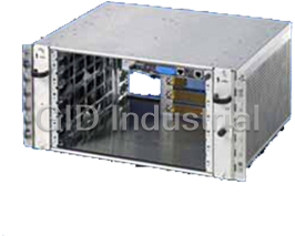
Due to its compact design, the 5 U shelf version offers optimum application possibilities, e.g. as a...
Due to its compact design, the 5 U shelf version offers optimum application possibilities, e.g. as a...

The Pixus Backplanes Division leverages designs from Kaparel, a leading innovator of AdvancedTCA des...
The 13U ATCA shelf design has over 15,000 global installs. This superior chassis design has been ado...
Request a Quote

The quote request has been received
Close

Facing challenges or have inquiries? Feel free to contact us!
Call Us +1-469-283-2440
What they say about us
FANTASTIC RESOURCE
One of our top priorities is maintaining our business with precision, and we are constantly looking for affiliates that can help us achieve our goal. With the aid of GID Industrial, our obsolete product management has never been more efficient. They have been a great resource to our company, and have quickly become a go-to supplier on our list!
Bucher Emhart Glass
EXCELLENT SERVICE
With our strict fundamentals and high expectations, we were surprised when we came across GID Industrial and their competitive pricing. When we approached them with our issue, they were incredibly confident in being able to provide us with a seamless solution at the best price for us. GID Industrial quickly understood our needs and provided us with excellent service, as well as fully tested product to ensure what we received would be the right fit for our company.
Fuji
HARD TO FIND A BETTER PROVIDER
Our company provides services to aid in the manufacture of technological products, such as semiconductors and flat panel displays, and often searching for distributors of obsolete product we require can waste time and money. Finding GID Industrial proved to be a great asset to our company, with cost effective solutions and superior knowledge on all of their materials, it’d be hard to find a better provider of obsolete or hard to find products.
Applied Materials
CONSISTENTLY DELIVERS QUALITY SOLUTIONS
Over the years, the equipment used in our company becomes discontinued, but they’re still of great use to us and our customers. Once these products are no longer available through the manufacturer, finding a reliable, quick supplier is a necessity, and luckily for us, GID Industrial has provided the most trustworthy, quality solutions to our obsolete component needs.
Nidec Vamco
TERRIFIC RESOURCE
This company has been a terrific help to us (I work for Trican Well Service) in sourcing the Micron Ram Memory we needed for our Siemens computers. Great service! And great pricing! I know when the product is shipping and when it will arrive, all the way through the ordering process.
Trican Well Service
GO TO SOURCE
When I can't find an obsolete part, I first call GID and they'll come up with my parts every time. Great customer service and follow up as well. Scott emails me from time to time to touch base and see if we're having trouble finding something.....which is often with our 25 yr old equipment.
ConAgra Foods