

 Manufacturers
SCHMERSAL 801000002

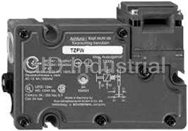
Description
Safety Switch, Interlock, Actuator, 2NC, Screw Connection, M16
The Series AZ15/16 is designed for use with movable machine guards/access gates which must be closed for operator safety. Their positive-opening NC contacts provide a significantly higher level of safety than conventional spring driven switches whose contacts can weld or stick shut. And their tamper-resistant design prevents bypassing with simple tools, bent wires or other readily available means. Their IP67 rating makes them ideal for interlocking safety guards in hostile environments.
Part Number
801000002
Price
Request Quote
Manufacturer
SCHMERSAL
Lead Time
Request Quote
Category
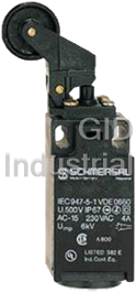
Safety » Switches
Specifications
Part Number
801000002
Product Series
AZ
Voltage
See Spec or N/A
Weight - lbs.
0.2500
Base Unit of Measure
Each
Categorization Information
Safety - Intrinsic, Curtains, Mats, etc.
Safety Switch, Interlock, Actuator, 2NC,-801000002
Features
- Thermoplastic enclosure
- Double-insulated
- Large wiring compartment
- 52 mm x 90 mm x 30 mm
- Multiple coding
- Long life
- High level of contact reliability with low voltages and currents
- Insensitive to soiling
- Slotted holes for adjustment, circular holes for location
- 3 cable entries M 16 x 1.5
- LED version available
Datasheet

Extracted Text
Operating instructions Safety switch AZ 15 / AZ 16 1 About this document 1.1 Function This operating instructions manual provides all the information you need for the mounting, set-up and commissioning to ensure the safe operation and disassembly of the safety switchgear. The operating inst- ructions must be available in a legible condition and a complete version EN Operating instructions...................... pages 1 to 4 in the vicinity of the device. Translation of the original operating instructions 1.2 Target group: authorised qualified personnel All operations described in this operating instructions manual must be carried out by trained specialist personnel, authorised by the plant Vous trouverez la version Encontrará el manual de operator only. FR ES actuelle du mode d’emploi dans instrucciones actual en su votre langue nationale officielle idioma oficial de la UE en nu- sur l’Internet, www.schmersal. estra página de Internet www. Please make sure that you have read and understood these operating net. schmersal.net. instructions and that you know all applicable legislations regarding occupational safety and accident prevention prior to installation and U vindt de huidige versie van Il manuale d‘istruzioni aggior- NL IT de gebruikshandleiding in uw nato nella vostra lingua (lingua putting the component into operation. officiële landstaal op het Inter- ufficiale UE) è scaricabile in net, www.schmersal.net. Internet all‘indirizzo www. schmersal.net. The machine builder must carefully select the harmonised standards to be complied with as well as other technical specifications for the selec- EU公用語で書かれた最新の JP tion, mounting and integration of the components. 取扱説明書は、インターネッ (www.schmersal.net)からダウ ンロードできます。 1.3 Explanation of the symbols used Information, hint, note: This symbol is used for identifying useful additional information. Caution: Failure to comply with this warning notice could Content lead to failures or malfunctions. Warning: Failure to comply with this warning notice could 1 About this document lead to physical injury and/or damage to the machine. 1.1 Function . . . . . . . . . . . . . . . . . . . . . . . . . . . . . . . . . . . . . . . . . . . . . .1 1.2 Target group: authorised qualified personnel. . . . . . . . . . . . . . . . . .1 1.3 Explanation of the symbols used . . . . . . . . . . . . . . . . . . . . . . . . . . .1 1.4 Appropriate use 1.4 Appropriate use . . . . . . . . . . . . . . . . . . . . . . . . . . . . . . . . . . . . . . . .1 The products described in these operating instructions are developed to 1.5 General safety instructions . . . . . . . . . . . . . . . . . . . . . . . . . . . . . . .1 execute safety-related functions as part of an entire plant or machine. It 1.6 Warning about misuse . . . . . . . . . . . . . . . . . . . . . . . . . . . . . . . . . . .2 is the responsibility of the manufacturer of a machine or plant to ensure 1.7 Exclusion of liability . . . . . . . . . . . . . . . . . . . . . . . . . . . . . . . . . . . . .2 the proper functionality of the entire machinery or plant. 2 Product description The safety switchgear must be exclusively used in accordance with the 2.1 Ordering code . . . . . . . . . . . . . . . . . . . . . . . . . . . . . . . . . . . . . . . . .2 versions listed below or for the applications authorised by the manufac- 2.2 Special versions. . . . . . . . . . . . . . . . . . . . . . . . . . . . . . . . . . . . . . . .2 turer. Detailed information regarding the range of applications can be 2.3 Destination and use . . . . . . . . . . . . . . . . . . . . . . . . . . . . . . . . . . . . .2 found in the chapter "Product description". 2.4 Technical data . . . . . . . . . . . . . . . . . . . . . . . . . . . . . . . . . . . . . . . . .2 2.5 Safety classification . . . . . . . . . . . . . . . . . . . . . . . . . . . . . . . . . . . . .2 1.5 General safety instructions The user must observe the safety instructions in this operating instruc- 3 Mounting tions manual, the country-specific installation standards as well as all 3.1 General mounting instructions . . . . . . . . . . . . . . . . . . . . . . . . . . . . .2 prevailing safety regulations and accident prevention rules. 3.2 Dimensions . . . . . . . . . . . . . . . . . . . . . . . . . . . . . . . . . . . . . . . . . . .3 Further technical information can be found in the Schmersal 4 Electrical connection catalogues or in the online catalogue on the Internet: www. 4.1 General information for electrical connection. . . . . . . . . . . . . . . . . .3 schmersal.net. 4.2 Contact variants. . . . . . . . . . . . . . . . . . . . . . . . . . . . . . . . . . . . . . . .3 The information contained in this operating instructions manual is provi- 5 Set-up and maintenance ded without liability and is subject to technical modifications. 5.1 Functional testing. . . . . . . . . . . . . . . . . . . . . . . . . . . . . . . . . . . . . . .3 5.2 Maintenance . . . . . . . . . . . . . . . . . . . . . . . . . . . . . . . . . . . . . . . . . .3 If multiple safety components are wired in series, the Perfor- 6 Disassembly and disposal mance Level to EN ISO 13849-1 will be reduced due to the 6.1 Disassembly. . . . . . . . . . . . . . . . . . . . . . . . . . . . . . . . . . . . . . . . . . .3 restricted error detection under certain circumstances. The 6.2 Disposal . . . . . . . . . . . . . . . . . . . . . . . . . . . . . . . . . . . . . . . . . . . . . .3 entire concept of the control system, in which the safety com- ponent is integrated, must be validated to EN ISO 13849-2. 7 Appendix 7.1 EC Declaration of conformity . . . . . . . . . . . . . . . . . . . . . . . . . . . . . .3 There are no residual risks, provided that the safety instructions as well as the instructions regarding mounting, commissioning, operation and maintenance are observed. EN 1 1 x.000 / v.A. / 07.2009 / BZ-Nr. 50094-135V900 / Teile-Nr. 1085359-EN / Ausgabe R Operating Instructions Safety switch AZ 15 / AZ 16 1.6 Warning about misuse The user must evaluate and design the safety chain in accordance with the relevant standards and on the required In case of inadequate or improper use or manipulations of the safety level. safety switchgear, personal hazards or damage to machinery or plant components cannot be excluded. The relevant requi- rements of the standard EN 1088 must be observed. 2.4 Technical data Standards: IEC/EN 60947-5-1, EN ISO 13849-1, 1.7 Exclusion of liability BG-GS-ET-15 We shall accept no liability for damages and malfunctions resulting from Enclosure: glass-fibre reinforced thermoplastic, defective mounting or failure to comply with this operating instructions self-extinguishing manual. The manufacturer shall accept no liability for damages resul- Actuator: stainless steel 1.4301 ting from the use of unauthorised spare parts or accessories. Protection class: IP 67 to IEC/EN 60529; DIN VDE 0470-1 For safety reasons, invasive work on the device as well as arbitrary re- Contact material: Silver pairs, conversions and modifications to the device are strictly forbidden; Contact types: AZ 15: 1 NC contact; AZ 16: change-over the manufacturer shall accept no liability for damages resulting from contact with double break Zb or 2 NC such invasive work, arbitrary repairs, conversions and/or modifications contacts or 3 NC contacts, with galvani- to the device. cally separated contact bridges Switching system: to IEC 60947-5-1; slow action, A positive break NC contact 2 Product description Connection: Screw connection or M 12 x 1 connector, 4 pole 2.1 Ordering code 2 Cable section: 0,25...2,5 mm (including conductor This operating instructions manual applies to the following types: ferrules) Cable entry: 3 x M16 x 1.5 AZ 15-ZV➀K-➁-➂ U : 6 kV No. Insert imp U : 500 V ➀ Ejection force i I : 10 A R Latching force 30 N the Utilisation category: AC-15 / DC-13 ➁ Cable entry M16 I /U : 4 A / 230 VAC 4 A / 24 VDC ST M12 x 1 connector e e Required short-circuit 1000 A ➂ 2254 Latching force 5 N current: 1762 Front mounting Max. fuse rating: 6 A gG D-fuse 1637 Gold-plated contacts Positive break travel: 8 mm Positive break force: each NC contact 10 N AZ 16-➀ZV➁K-➂-➃-➄ Ambient temperature: – 30 °C … + 80 °C ➀ 1 NO / 1 NC contact Mechanical life: >1 million operations 02 2 NC contacts Latching force: 30 N for ordering suffix R 03 3 NC contacts Actuating speed: max. 0,2 m/s 12 1 NO / 2 NC contact Max. switching frequency: 4000 operations / h ➁ Ejection force R Latching force 30 N ➂ G24 with LED ➃ Cable entry M16 2.5 Safety classification M20 Cable entry M20 ST M12 x 1 connector bottom Standards: EN ISO 13849-1 STL M12 x 1 connector LHS B (NC contact): 2,000,000 10d STR M12 x 1 connector RHS B (NO contact) at 10% ohmic 1,000,000 10d ➄ 2254 Latching force 5 N contact load: 1762 Front mounting B d x h x 3600 s/h 10d op op 1637 Gold-plated contacts nop MTTF d 0,1 x n t op cycle Only if the information described in this operating instructions (Specifications can vary depending on the application-specific parame- manual are realised correctly, the safety function and therefo- ters h , d and t as well as the load.) re the compliance with the Machinery Directive is maintained. op op cycle 2.2 Special versions 3 Mounting For special versions, which are not listed in the order code below 2.1, these specifications apply accordingly, provided that they correspond to 3.1 General mounting instructions the standard version. The mounting dimensions are indicated on the rear of the component. The switch enclosure must not be used as end stop. Any mounting 2.3 Destination and use position. The mounting position however must be chosen so that the The safety switches with separate actuator are suitable for sliding, ingression of dirt and soiling in the used opening is avoided. The unused hinged and removable safety guards, which need to be closed in order openings must be sealed by means of slot sealing plugs (AZ 15/16 - to ensure the necessary operational safety. 1476-1 available as accessory) after fitting. The safety switches are used for applications, in which the hazardous Mounting of the actuators: See mounting instructions actuators. situation is terminated without delay when the safety guard is opened. When the safety guard is opened, the NC contacts are positively ope- ned and the NO contacts are closed. 2 EN Operating Instructions Safety switch AZ 15 / AZ 16 4.2 Contact variants Please observe the remarks of the standards EN ISO 12100, Contacts are shown with safety guard closed. EN 953 and EN 1088. 11 12 11 12 3.2 Dimensions All measurements in mm. 1 2 3 4 AZ 15 / AZ 16 AZ 15ZVK AZ 15ZVK-ST AZ 15ZVRK AZ 15ZVRK-ST 40 40 13 14 11 12 13 14 11 12 21 22 21 22 21 22 21 22 31 32 31 32 AZ 16ZVK AZ 16-02ZVK AZ 16-12ZVK AZ 16-03ZVK AZ 16ZVRK AZ 16-02ZVRK AZ 16-12ZVRK AZ 16-03ZVRK M16 M16 13 14 11 12 M16 52 21 22 21 22 28 52 28 1 2 3 4 1 2 3 4 AZ 16ZVK-ST AZ 16-02ZVK-ST AZ 16ZVRK-ST AZ 16-02ZVRK-ST AZ 15 AZ 16 LED Front mounting 13 14 L+ 13 YE GN 24VDC 14 15 YE GN L- 15 5 Set-up and maintenance 5.1 Functional testing The safety function of the safety components must be tested. The 4 Electrical connection following conditions must be previously checked and met: 1. Check the free movement of the actuating element 2. Check the integrity of the cable entry and connections 4.1 General information for electrical connection 3. Check the switch enclosure for damage 5.2 Maintenance The electrical connection may only be carried out by autho- A regular visual inspection and functional test, including the following rised personnel in a de-energised condition. steps, is recommended: 1. Check the free movement of the actuating element The contact labelling can be found in the wiring compartment of the 2. Remove particles of dust and soiling switch. For the cable entry, suitable cable glands with an appropriate 3. Check cable entry and connections degree of protection must be used. After wiring, dust and soiling must be removed from the wiring compartment. The safety switch is double Damaged or defective components must be replaced. insulated. The use of a protective ground connector therefore is not authorised. 6 Disassembly and disposal 6.1 Disassembly The safety switchgear must be disassembled in a de-energised condi- tion only. 6.2 Disposal The safety switchgear must be disposed of in an appropriate manner in accordance with the national prescriptions and legislations. EN 3 75 30 18 8 8 ø5,5 90 30 18 8 8 ø5,5 Operating Instructions Safety switch AZ 15 / AZ 16 7 Appendix 7.1 EC Declaration of conformity EC Declaration of conformity Translation of the original declaration of K.A. Schmersal GmbH conformity Industrielle Sicherheitsschaltsysteme Möddinghofe 30 ▪ 42279 Wuppertal Germany Internet: www.schmersal.com We hereby certify that the hereafter described safety components both in its basic design and construction conform to the applicable European Directives. Name of the safety component / type: AZ 15 / AZ 16 Description of the safety component: Positive break position switch with separate actuator for safety functions Harmonised EC-Directives: 2006/42/EC EC-Machinery Directive Person authorized for the compilation of the Ulrich Loss technical documentation: Möddinghofe 30 42279 Wuppertal Place and date of issue: Wuppertal, 11. May 2009 Authorised signature Heinz Schmersal Managing Director Note The currently valid declaration of conformity can be downloa- ded from the internet at www.schmersal.net. K. A. Schmersal GmbH Industrielle Sicherheitsschaltsysteme Möddinghofe 30, D - 42279 Wuppertal Postfach 24 02 63, D - 42232 Wuppertal Telefon +49 - (0)2 02 - 64 74 - 0 Telefax +49 - (0)2 02 - 64 74 - 1 00 E-Mail: info@schmersal.com Internet: http://www.schmersal.com 4 EN Index B-EN
Frequently asked questions
Why choose IPC Station?

What is IPC Station' warranty policy for the 801000002?
What carriers does IPC Station use to ship parts?
Does IPC Station sell to international (non-USA) customers?
What methods of payment does IPC Station accept?
Why buy from GID?

Quality
We are industry veterans who take pride in our work

Protection
Avoid the dangers of risky trading in the gray market

Access
Our network of suppliers is ready and at your disposal

Savings
Maintain legacy systems to prevent costly downtime

Speed
Time is of the essence, and we are respectful of yours
Related Products
Request a Quote

The quote request has been received
Close

Facing challenges or have inquiries? Feel free to contact us!
Call Us +1-469-283-2440
What they say about us
FANTASTIC RESOURCE
One of our top priorities is maintaining our business with precision, and we are constantly looking for affiliates that can help us achieve our goal. With the aid of GID Industrial, our obsolete product management has never been more efficient. They have been a great resource to our company, and have quickly become a go-to supplier on our list!
Bucher Emhart Glass
EXCELLENT SERVICE
With our strict fundamentals and high expectations, we were surprised when we came across GID Industrial and their competitive pricing. When we approached them with our issue, they were incredibly confident in being able to provide us with a seamless solution at the best price for us. GID Industrial quickly understood our needs and provided us with excellent service, as well as fully tested product to ensure what we received would be the right fit for our company.
Fuji
HARD TO FIND A BETTER PROVIDER
Our company provides services to aid in the manufacture of technological products, such as semiconductors and flat panel displays, and often searching for distributors of obsolete product we require can waste time and money. Finding GID Industrial proved to be a great asset to our company, with cost effective solutions and superior knowledge on all of their materials, it’d be hard to find a better provider of obsolete or hard to find products.
Applied Materials
CONSISTENTLY DELIVERS QUALITY SOLUTIONS
Over the years, the equipment used in our company becomes discontinued, but they’re still of great use to us and our customers. Once these products are no longer available through the manufacturer, finding a reliable, quick supplier is a necessity, and luckily for us, GID Industrial has provided the most trustworthy, quality solutions to our obsolete component needs.
Nidec Vamco
TERRIFIC RESOURCE
This company has been a terrific help to us (I work for Trican Well Service) in sourcing the Micron Ram Memory we needed for our Siemens computers. Great service! And great pricing! I know when the product is shipping and when it will arrive, all the way through the ordering process.
Trican Well Service
GO TO SOURCE
When I can't find an obsolete part, I first call GID and they'll come up with my parts every time. Great customer service and follow up as well. Scott emails me from time to time to touch base and see if we're having trouble finding something.....which is often with our 25 yr old equipment.
ConAgra Foods