

 Manufacturers
SCHMERSAL 101208309
Description
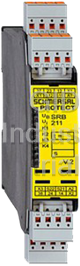
Safety Controller, 24VDC, LED, 2 Safety Contacts, 1 Signalling Output
Schmersal SRB Safety Controller for integration in safety circuits are designed for fitting in control cabinets. They are used for the safe evaluation of the signals of positive break position switches for safety functions on sliding, hinged and removable safety guards as well as emergency stop control devices.
Part Number
101208309
Price
Request Quote
Manufacturer
SCHMERSAL
Lead Time
Request Quote
Category
Safety » Controllers
Specifications
Part Number
101208309
Product Series
SRB
Voltage
24VDC
Weight - lbs.
0.5500
Base Unit of Measure
Each
Categorization Information
Safety - Intrinsic, Curtains, Mats, etc.
Safety Controller, 24VDC, LED,-101208309
Datasheet

Extracted Text
25.02.2016 - 19:59:34h Datasheet - SRB 211ST V.2 Guard door monitors and Safety control modules for Emergency Stop applications / Micro Processor based safety controllers (Series AES) / SRB211ST Preferred typ • 2 safety contacts, STOP 0; 1 safety contact, STOP 1 • 1 Signalling output • Suitable for signal processing of potential-free outputs, e.g. emergency stop command devices, position switches and solenoid interlocks • Suitable for signal processing of outputs connected to potentials (AOPDs), e.g. safety light grids/curtains (Minor differences between the printed image and the original product may exist!) Ordering details Product type description SRB 211ST V.2 Article number 101208309 EAN code eCl@ss 27-37-19-01 Approval Approval BG USA/CAN Classification Standards EN ISO 13849-1, IEC 61508, EN 60947-5-1 PL up e (STOP 0) bis d (STOP 1) Control category up 4 (STOP 0) up 3 (STOP 1) DC 99% (STOP 0) > 60% (STOP 1) CCF > 65 points PFH value ≤ 2,0 x 10⁻⁸/h (STOP 0) ≤ 2,0 x 10⁻⁷/h (STOP 1) SIL up 3 (STOP 0) bis 2 (STOP 1) Mission time 20 Years - notice The PFH value is applicable for the combinations listed in the table for contact load (K) (current through enabling paths) and switching cycle number (n-op/y). In case of 365 operating days per year and a 24-hour operation, this results in the specified switching cycle times (t-cycle) for the relay contacts. Diverging applications on request. Global Properties Product name SRB 211ST Standards IEC/EN 60204-1, EN 60947-5-1, EN ISO 13849-1, IEC 61508 Compliance with the Directives (Y/N) Yes Climatic stress EN 60068-2-78 Mounting snaps onto standard DIN rail to EN 60715 Terminal designations IEC/EN 60947-1 Materials - Material of the housings Plastic, glass-fibre reinforced thermoplastic, ventilated - Material of the contacts , Ag-Ni, self-cleaning, positive action Weight 250 g Start conditions Automatic or Start button (Optional monitored) Start input (Y/N) Yes Feedback circuit (Y/N) Yes Start-up test (Y/N) No Reset after disconnection of supply voltage (Y/N) No Automatic reset function (Y/N) Yes Reset with edge detection (Y/N) Yes Pull-in delay - ON delay with automatic start 120 ms - ON delay with reset button ≤ 25 ms Drop-out delay - Drop-out delay in case of power failure ≤ 55 ms - Drop-out delay in case of emergency stop 15 ms, max. 20 ms Mechanical data Connection type Screw connection Cable section - Min. Cable section 0,25 mm² - Max. Cable section 2.5 mm² Pre-wired cable rigid or flexible Tightening torque for the terminals 0,6 Nm Detachable terminals (Y/N) Yes Mechanical life 10.000.000 operations Electrical lifetime Derating curve available on request restistance to shock 30 g / 11 ms Resistance to vibration To EN 60068-2-6 10...55 Hz, Amplitude 0,35 mm, ± 15 % Ambient conditions Ambient temperature - Min. environmental temperature −25 °C - Max. environmental temperature +60 °C Storage and transport temperature - Min. Storage and transport temperature −40 °C - Max. Storage and transport temperature +85 °C Protection class - Protection class-Enclosure IP40 - Protection class-Terminals IP20 - Protection class-Clearance IP54 Air clearances and creepage distances To IEC/EN 60664-1 - Rated impulse withstand voltage Uimp 4 kV - Overvoltage category III To VDE 0110 - Degree of pollution 2 To VDE 0110 Electromagnetic compatibility (EMC) EMC rating conforming to EMC Directive Electrical data Rated DC voltage for controls - Min. rated DC voltage for controls 20.4 V - Max. rated DC voltage for controls 28.8 V Rated AC voltage for controls, 50 Hz - Min. rated AC voltage for controls, 50 Hz 20.4 V - Max. rated AC voltage for controls, 50 Hz 26.4 V Rated AC voltage for controls, 60 Hz - Min. rated AC voltage for controls, 60 Hz 20.4 V - Max. rated AC voltage for controls, 60 Hz 26.4 V Contact resistance max. 100 mΩ Power consumption 2.4 W; 5.9 VA, plus signalling output Type of actuation AC/DC Rated operating voltage Ue 24 VDC −15% / +20%, residual ripple max. 10%; 24 VAC −15% / +10% Operating current Ie 0,24 A Frequency range 50 / 60 Hz Electronic protection (Y/N) Yes Fuse rating for the operating voltage Internal electronic trip, tripping current F1: > 750 mA, tripping current F2: > 75 mA Reset after disconnection of supply voltage tripping current F3: > 140 mA Current and tension on control circuits - S11, S12, S21, S22 24 VDC, Test current: 10 mA - X1, X2 24 VDC, Test current: 10 mA, Start pulse: 25 mA / 25 ms - X1, X3 24 VDC, Test current: 10 mA, Start pulse: 950 mA / 10 ms Bridging in case of voltage drops 40 ms Inputs Monitored inputs - Short-circuit recognition (Y/N) optional - Wire breakage detection (Y/N) Yes - Earth connection detection (Y/N) Yes Number of shutters 0 piece Number of openers 2 piece Cable length 1500 m with 1.5 mm²; 2500 m with 2.5 mm² Conduction resistance max. 40 Ω Outputs Stop category 0 / 1 - Stop category 0 13-14, 23-24: AC-15: 230 V / 6 A DC-13: 24 V / 5 A Number of safety contacts 3 piece Number of auxiliary contacts 0 piece Number of signalling outputs 1 piece Switching capacity - Switching capacity of the safety contacts (13-14; 23-24) max. 250 V, 8 A ohmic (inductive in case of appropriate protective wiring) min. 5 V, 5 mA (37-38) max. 250 V, 6 A ohmic (inductive in case of appropriate protective wiring) min. 10 V, 10 mA - Switching capacity of the signaling/diagnostic outputs 24 VDC, 100 mA Fuse rating - Protection of the safety contacts 8 A slow blow (13-14; 23-24) 6.3 A slow blow ( 37-38) - Fuse rating for the signaling/diagnostic outputs Internal electronic trip tripping current > 0,1 A Utilisation category To EN 60947-5-1 - Stop category 1 37-38: AC-15: 230 V / 3 A DC-13: 24 V / 2 A Number of undelayed semi-conductor outputs with signaling function 1 piece Number of undelayed outputs with signaling function (with contact) 0 piece Number of delayed semi-conductor outputs with signaling function. 0 piece Number of delayed outputs with signalling function (with contact). 0 piece Number of secure undelayed semi-conductor outputs with signaling function 0 piece Number of secure, undelayed outputs with signaling function, with contact. 2 piece Number of secure, delayed semi-conductor outputs with signaling function 0 piece Number of secure, delayed outputs with signaling function (with contact). 1 piece LED switching conditions display LED switching conditions display (Y/N) Yes Number of LED´s 6 piece LED switching conditions display - The integrated LEDs indicate the following operating states. - Position relay K2 - Position relay K1 - Position relay K3/K4 - Supply voltage - Internal operating voltage Ui Miscellaneous data Applications Emergency-Stop button Pull-wire emergency stop switches Guard system Safety light curtain Safety sensor Dimensions Dimensions - Width 22.5 mm - Height 100 mm - Depth 121 mm notice Inductive loads (e.g. contactors, relays, etc.) are to be suppressed by means of a suitable circuit. notice - Wiring example Input level: The example shows a 2-channel control of a guard door monitoring with two position switches, whereof one with positive break, external reset button (R) and feedback circuit (H2). The control recognises cross-short, cable break and earth leakages in the monitoring circuit. F1 = hybrid fuse Relay outputs: Suitable for 2 channel control, for increase in capacity or number of contacts by means of contactors or relays with positive-guided contacts. For 1-channel control, connect NC contact to S11/S12 and bridge S12/S22 Connect potential p-type outputs of safety light grids/curtains to S12/S22. The devices must have the same reference potential. Automatic start: The automatic start is programmed by connecting the feedback circuit to the terminals X1/X3. If the feedback circuit is not required, establish a bridge Time delay: The time-delayed safety enable 37/38 is adjustable for 1 to 30 seconds drop-out delay (see setting intructions). The safety enabling circuit 37/38 conforms to EN 60204-1 for STOP Category 1. The safety enabling circuits 13/14 and 23/24 conform to EN 60204-1 for STOP Category 0. Setting of the drop-out delay time is carried out by means of a potentiometer from the front of the enclosure. The wiring diagram is shown with guard doors closed and in de-energised condition. Documents Operating instructions and Declaration of conformity (pt) 1 MB, 02.08.2012 Code: mrl_srb_ 211st_v2_pt Operating instructions and Declaration of conformity (en) 587 kB, 13.09.2013 Code: mrl_srb_ 211st_v2_en Operating instructions and Declaration of conformity (pl) 625 kB, 18.03.2014 Code: mrl_srb_ 211st_v2_pl Operating instructions and Declaration of conformity (it) 590 kB, 06.11.2013 Code: mrl_srb_ 211st_v2_it Operating instructions and Declaration of conformity (es) 594 kB, 07.11.2013 Code: mrl_srb_ 211st_v2_es Operating instructions and Declaration of conformity (nl) 603 kB, 28.01.2014 Code: mrl_srb_ 211st_v2_nl Operating instructions and Declaration of conformity (sv) 1 MB, 10.09.2012 Code: mrl_srb_ 211st_v2_sv Operating instructions and Declaration of conformity (da) 598 kB, 14.10.2015 Code: mrl_srb_ 211st_v2_da Operating instructions and Declaration of conformity (de) 596 kB, 13.09.2013 Code: mrl_srb_ 211st_v2_de Operating instructions and Declaration of conformity (jp) 697 kB, 07.11.2013 Code: mrl_srb_ 211st_v2_jp Operating instructions and Declaration of conformity (fr) 594 kB, 06.11.2013 Code: mrl_srb_ 211st_v2_fr Operating instructions and Declaration of conformity (cs) 1 MB, 27.02.2012 Code: mrl_srb_ 211st_v2_cs Wiring example (99) 19 kB, 04.08.2008 Code: Ksrb2l03 BG-test certificate (de) 818 kB, 14.01.2015 Code: z_211p01 BG-test certificate (en) 806 kB, 14.01.2015 Code: z_211p02 CCC certification (cn) 87 kB, 24.09.2015 Code: q_srbp08 CCC certification (en) 121 kB, 24.09.2015 Code: q_srbp07 Images Wiring example K.A. Schmersal GmbH & Co. KG, Möddinghofe 30, D-42279 Wuppertal The data and values have been checked throroughly. Technical modifications and errors excepted. Generiert am 25.02.2016 - 19:59:35h Kasbase 3.2.1.F.64I
Frequently asked questions
Why choose IPC Station?

What is IPC Station' warranty policy for the 101208309?
What carriers does IPC Station use to ship parts?
Does IPC Station sell to international (non-USA) customers?
What methods of payment does IPC Station accept?
Why buy from GID?

Quality
We are industry veterans who take pride in our work

Protection
Avoid the dangers of risky trading in the gray market

Access
Our network of suppliers is ready and at your disposal

Savings
Maintain legacy systems to prevent costly downtime

Speed
Time is of the essence, and we are respectful of yours
Related Products
Request a Quote

The quote request has been received
Close

Facing challenges or have inquiries? Feel free to contact us!
Call Us +1-469-283-2440
What they say about us
FANTASTIC RESOURCE
One of our top priorities is maintaining our business with precision, and we are constantly looking for affiliates that can help us achieve our goal. With the aid of GID Industrial, our obsolete product management has never been more efficient. They have been a great resource to our company, and have quickly become a go-to supplier on our list!
Bucher Emhart Glass
EXCELLENT SERVICE
With our strict fundamentals and high expectations, we were surprised when we came across GID Industrial and their competitive pricing. When we approached them with our issue, they were incredibly confident in being able to provide us with a seamless solution at the best price for us. GID Industrial quickly understood our needs and provided us with excellent service, as well as fully tested product to ensure what we received would be the right fit for our company.
Fuji
HARD TO FIND A BETTER PROVIDER
Our company provides services to aid in the manufacture of technological products, such as semiconductors and flat panel displays, and often searching for distributors of obsolete product we require can waste time and money. Finding GID Industrial proved to be a great asset to our company, with cost effective solutions and superior knowledge on all of their materials, it’d be hard to find a better provider of obsolete or hard to find products.
Applied Materials
CONSISTENTLY DELIVERS QUALITY SOLUTIONS
Over the years, the equipment used in our company becomes discontinued, but they’re still of great use to us and our customers. Once these products are no longer available through the manufacturer, finding a reliable, quick supplier is a necessity, and luckily for us, GID Industrial has provided the most trustworthy, quality solutions to our obsolete component needs.
Nidec Vamco
TERRIFIC RESOURCE
This company has been a terrific help to us (I work for Trican Well Service) in sourcing the Micron Ram Memory we needed for our Siemens computers. Great service! And great pricing! I know when the product is shipping and when it will arrive, all the way through the ordering process.
Trican Well Service
GO TO SOURCE
When I can't find an obsolete part, I first call GID and they'll come up with my parts every time. Great customer service and follow up as well. Scott emails me from time to time to touch base and see if we're having trouble finding something.....which is often with our 25 yr old equipment.
ConAgra Foods