

 Manufacturers
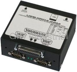
PORTWELL USB-IIRO4-DB
Description
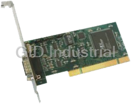
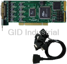
USB 4-port hub internally to provide four optically isolated digital inputs and four electromechanical relay outputs in a small rugged enclosure with DB25 connector.
Part Number
USB-IIRO4-DB
Price
Request Quote
Manufacturer
PORTWELL
Lead Time
Request Quote
Category
I/O Products
Specifications
Categorization Information
IO Products
Features
- Multifunction I/O adapter for USB 1.1 and 2.0 port hosts
- Four optically isolated digital inputs
- Four Form C electromechanical 1A relays
- Two serial ports, field selectable RS-232/422/485
- Small (4" x4" X1.8") rugged industrial enclosure
- PC/104 module size and mounting compatibility
- All required power drawn from USB port, no external power adapter required
- Expansion USB hub port connector
Datasheet

Extracted Text
C C C MODEL USB-IIRO4-2SM USER MANUAL FILE: MUSB-IIRO4-2SM.A1l Notice The information in this document is provided for reference only. Portwell does not assume any liability arising out of the application or use of the information or products described herein. This document may contain or reference information and products protected by copyrights or patents and does not convey any license under the patent rights of Portwell, nor the rights of others. IBM PC, PC/XT, and PC/AT are registered trademarks of the International Business Machines Corporation. Printed in USA. Copyright 2006 by Portwell I/O Products Inc. All rights reserved. WARNING!! ALWAYS CONNECT AND DISCONNECT YOUR FIELD CABLING WITH THE COMPUTER POWER OFF. ALWAYS TURN COMPUTER POWER OFF BEFORE INSTALLING A CARD. CONNECTING AND DISCONNECTING CABLES, OR INSTALLING CARDS INTO A SYSTEM WITH THE COMPUTER OR FIELD POWER ON MAY CAUSE DAMAGE TO THE I/O CARD AND WILL VOID ALL WARRANTIES, IMPLIED OR EXPRESSED. 2 Manual USB-IIRO4-2SM Warranty Prior to shipment, Portwell equipment is thoroughly inspected and tested to applicable specifications. However, should equipment failure occur, Portwell assures its customers that prompt service and support will be available. All equipment originally manufactured by Portwell which is found to be defective will be repaired or replaced subject to the following considerations. Terms and Conditions If a unit is suspected of failure, contact Portwell' Customer Service department. Be prepared to give the unit model number, serial number, and a description of the failure symptom(s). We may suggest some simple tests to confirm the failure. We will assign a Return Material Authorization (RMA) number which must appear on the outer label of the return package. All units/components should be properly packed for handling and returned with freight prepaid to the Portwell designated Service Center, and will be returned to the customer's/user's site freight prepaid and invoiced. Coverage First Three Years: Returned unit/part will be repaired and/or replaced at Portwell option with no charge for labor or parts not excluded by warranty. Warranty commences with equipment shipment. Following Years: Throughout your equipment's lifetime, Portwell stands ready to provide on-site or in-plant service at reasonable rates similar to those of other manufacturers in the industry. Equipment Not Manufactured by Portwell Equipment provided but not manufactured by Portwell is warranted and will be repaired according to the terms and conditions of the respective equipment manufacturer's warranty. General Under this Warranty, liability of Portwell is limited to replacing, repairing or issuing credit (at Portwell discretion) for any products which are proved to be defective during the warranty period. In no case is Portwell liable for consequential or special damage arriving from use or misuse of our product. The customer is responsible for all charges caused by modifications or additions to Portwell equipment not approved in writing by Portwell or, if in Portwell opinion the equipment has been subjected to abnormal use. "Abnormal use" for purposes of this warranty is defined as any use to which the equipment is exposed other than that use specified or intended as evidenced by purchase or sales representation. Other than the above, no other warranty, expressed or implied, shall apply to any and all such equipment furnished or sold by Portwell. 3 Manual USB-IIRO4-2SM TABLE OF CONTENTS Chapter 1: Introduction ............ ............ ............ ............ ............ .. 5 Communication Mode ............ ............ ............ ............ .......... 6 Figure 1-1: Block Diagram ............ ............ ............ ............ 9 Chapter 2: Installation ............ ............ ............ ............ ............ .. 10 Hardware Installation ............ ............ ............ ............ .......... 10 Chapter 3: Option Selection ............ ............ ............ ............ ......... 11 Figure 3-1: Option Selection Map ............ ............ ............ ...... 12 Chapter 4: Address Selection ............ ............ ............ ............ ........ 13 Chapter 5: Programming ............ ............ ............ ............ ............ 14 Chapter 6: Connector Pin Assignments ............ ............ ............ ........... 15 Table 6-1: IIRO Connector Pin Assignments ............ ............ ......... 15 Table 6-2: DB25 Pinout ............ ............ ............ ............ . 16 Table 6-3: Serial Connector Pin Assignments ............ ............ ........ 17 4 Manual USB-IIRO4-2SM Chapter 1: Introduction The USB-IIRO4-2SM is a USB multifunction device, incorporating a USB 4-port hub internally to provide both Isolated I/O and Serial Communication features in one product. The following paragraphs will first describe the Onboard Serial ports, followed by the Isolated Input and Relay Output features. Serial Communication This Serial Adapter was designed for effective multipoint transmission in any one of three modes on each channel. These modes are RS232, RS422 and RS485 (EIA485) protocol. The card features two independent, asynchronous serial ports. RS422 Balanced Mode Operation The board supports RS422 communications and uses differential balanced drivers for long range and noise immunity. The board also has the capability to add load resistors to terminate the communications lines. RS422 communications requires that a transmitter supply a bias voltage to ensure a known "zero" state. Also, receiver inputs at each end of the network should be terminated to eliminate "ringing". The board supports biasing by default and supports termination by jumpers on the card. If your application requires the transmitter to be un-biased, please contact the factory. RS485 Balanced Mode Operation The board supports RS485 communications and uses differential balanced drivers for long range and noise immunity. RS485 operation involves switchable transceivers and the ability to support multiple devices on a single "party line". The RS485 specification defines a maximum of 32 devices on a single line. The number of devices served on a single line can be expanded by use of "repeaters". This board also has the capability to add load resistors to terminate the communications lines. RS485 communications requires that one transmitter supply a bias voltage to ensure a known "zero" state when all transmitters are off. Also, receiver inputs at each end of the network should be terminated to eliminate "ringing". The card supports biasing by default and supports termination by jumpers on the card. If your application requires the transmitter to be un-biased, please contact the factory. COM Port Compatibility The FT232BM UARTs are used as Asynchronous Communication Elements (ACE). These include 128- byte transmit & 384-byte receive buffers to protect against lost data in multitasking operating systems, while maintaining 100 percent compatibility with the original IBM serial port. The system assigns the address(es). A crystal oscillator is located on the board. This oscillator permits precise selection of baud rate up to 921.6K bps. The driver/receiver used (SP491 in non-RS232 modes) is capable of driving extremely long communication lines at high baud rates. It can drive up to +60 mA on balanced lines and receive inputs as low as 200 mV differential signal superimposed on common mode noise of +12 V or -7 V. In case of com munication conflict, the driver/receivers feature thermal shutdown. The driver/receiver used in RS232 mode is the ICL3243. 5 Manual USB-IIRO4-2SM Communication Mode The board supports Half-Duplex communications with a 2-wire cable connection. Half-Duplex allows traffic to travel in both directions, but only one way at a tim e. RS485 com munications commonly use the Half-Duplex mode since they share only a single pair of wires. Baud Rate Ranges The board has capability for baud rates up to 921.6K bps. Serial Specifications Communications Interface • I/O Connection: Standard USB connector • Serial Ports: 2 male D-sub 9-pin connectors • Character length: 5, 6, 7, or 8 bits. • Parity: Even, odd or none. • Stop Interval: 1, 1.5, or 2 bits. • Serial Data Rates: Up to 921.6K • Receiver Input Sensitivity: +200 mV, differential input. • Common Mode Rejection: +12V to -7V • Transmitter Output Drive Capability: 60 mA, with thermal shutdown. Bus Type USB 1.1, USB 2.0 Host Compatible Environmental • Operating Temperature Range: 0 /C. to +60 /C. • Storage temperature Range: -50 /C. to +120 /C. • Hum idity: 5% to 95%, non-condensing. • Power Required: 120mA Quiescent, 320mA maximum (see below) +20mA for each activated relay (80 max) Current: 0-60mA per com channel • Size: 4 inches wide by 4 inches deep by 1.25 inches high 6 Manual USB-IIRO4-2SM Isolated Functionality This board is an ideal solution for adding portable, easy-to-install digital I/O to any computer with a USB port. This is a USB 1.1 device, compatible with both USB 1.1 and USB 2.0 ports. The board is plug-and-play allowing for quick connect/disconnect whenever you need additional I/O on your computer. Inputs The board provides four optically-isolated inputs. These inputs can accept either AC or DC signals and are not polarity sensitive. Input signals are rectified by photocoupler diodes while unused power gets dissipated through a 1.8k-ohm resistor in series. The inputs may be driven by either DC sources of 3 to 31 volts (rms) or AC sources at frequencies of 40 Hz to 10 KHz. Standard 12/24 AC control transformer outputs can be accepted as well. External resistors connected in series may be used to extend the input voltage range, however this will raise the input threshold range. Consult with factory for available modified input ranges. Each input circuit contains a switchable filter that has a 4.7 millisecond time constant. (Without filtering, the response is less then 40 microseconds) The filter must be selected for AC inputs in order to eliminate the on/off response to AC. The filter is also valuable for use with slow DC input signals in a noisy environment. The filter may be switched out for DC inputs in order to obtain faster response. Filters are individually selected by jumpers. The filters are switched into the circuit when the jumpers are installed in position IPFLT0 to IPFLT3. Outputs The board's outputs are comprised of four FORM C SPDT electro mechanical relays. These relays are all de-energized at power-on. USB Connector The USB connector is a Type B connector and mates with the cable provided. The USB port provides communication signals along with +5 VDC power. The board is powered from the USB port or alternate USB connector. A second USB Input Connector (P4) in parallel to the Type B connector is supplied. This second connector is a USB (OTG) connector. LED There are four LEDs present on the product, functioning as follows: Indicator Function 1 USB Power Present 2 USB Digital I/O Enabled / Ready 3 Serial Port 1 Activity 4 Serial Port 2 Activity 7 Manual USB-IIRO4-2SM Isolated Input Relay Output Specifications Isolated Inputs • Number of inputs: 4 • Type: Non-polarized, optically isolated from each other and from the computer (CMOS compatible) • Voltage Range: 3 to 31 DC or AC Rms (40 to 10000 Hz) • Isolation: 500V*(see note) channel-to-ground or channel-to channel • Input Resistance: 1.8K ohms in series with opto coupler • Filter Response Times: Rise Time = 4.7 mS / Fall Time = 4.7 mS • Non-Filter Response Times: Rise Time = 10 uS / Fall Time = 30 uS *Notes on Isolation: Opto-Isolators and connectors are rated for at least 500V, but isolation voltage breakdowns will vary and is affected by factors like cabling, spacing of pins, spacing between traces on the PCB, humidity, dust and other environmental factors. This is a safety issue so a careful approach is required. For CE certification, isolation was specified at 40V AC and 60V DC. The design intention was to eliminate the influence of common mode. Use proper wiring techniques to minimize voltage between channels and to ground. For example, when working with AC voltages do not connect the hot side of the line to an input. Tolerance of higher isolation voltage can be obtained on request by applying a conformal coating to the board. Relay Outputs • Number of outputs: 4 SPDT form C • Contact Type: Single crossbar; Ag with Au clad • Rated Load AC: 0.5 A at 125 VAC (62.5 VA max.) • Rated Load DC: 1A at 24 VDC (30 W max.) • Max. Switching Voltage: 125 VAC, 60 VDC • Max. Switching Current: 1 A • Contact Resistance: 100 mS max. • Contact Life: mech'l: 5 million operations min. • Operating Time: 5 milliseconds max. • Release Time: 5 milliseconds max. Auxiliary USB Connector This board has an optional feature. You can cable an extra USB type A connector to the onboard USB1.1 hub. This would provide an additional, "daisy-chained" USB 1.1 bus to which you can attach any 3rd party USB devices you may wish. 8 Manual USB-IIRO4-2SM Figure 1-1: Block Diagram 9 Manual USB-IIRO4-2SM Chapter 2: Installation Software CD Installation These paragraphs are intended to detail the software installation steps as well as describe what is being installed. The software provided with this board is contained on one CD and must be installed onto your hard disk prior to use. To do this, perform the following steps as appropriate for your software format and operating system. Substitute the appropriate drive letter for your CD-ROM or disk drive where you see d: in the examples below. WIN95/98/Me/NT/2000/XP/2003 a. Place the CD into your CD-ROM drive. b. The CD should automatically run the install program. If the install program does not click START | RUN and type d:install, click OK or press K . c. Follow the on-screen prompts to install the software for this board. LINUX 1. Please refer to linux.htm on the CD-ROM for information on installing under linux. Hardware Installation The board can be installed in any USB 2.0 or USB 1.1 port. Please install the software package before plugging the hardware into the system. 10 Manual USB-IIRO4-2SM Chapter 3: Option Selection Refer to the setup programs on the CD provided with the board. Also, refer to the Block diagram and the Option Selection Map when reading this section of the manual. Terminations A transmission line should be terminated at the receiving end in its characteristic impedance. Installing a jumper at the locations labeled RS485-LD applies a 120S load across the transmit/receive input/output for RS485 operation. Jumpers having to do with the termination of each channel are located near the output connector. They are labeled by channel. The load jumper is labeled “TERM”. The other two jumpers are used to connect the transmit and receive lines for the two wire RS485 mode. In RS485 operations where there are multiple terminals, only the RS485 ports at each end of the network should have terminating impedance as described above. To terminate the COM A port, place a jumper at the location labeled Ch A - RS485. To terminate the COM B port place jumpers at the location labeled Ch B - RS485. Also, for RS485 operation, there must be a bias on the TRX+ and TRX- lines. If the adapter is not to provide that bias, consult the factory for technical support. Data Cable Wiring Signal Pin Connection Ain/out+ 2 Ain/o ut- 3 100S to Ground 5 Filter Response Switch Jumpers are used to select input filtering on a channel-by-channel basis. When jumper FLT0 is installed, additional filtering is introduced for bit 0, FLT 1 for bit 1, etc. Jumper Selection Bit Filtered FLT-0 IN00 FLT-1 IN01 FLT-2 IN02 FLT-3 IN03 11 Manual USB-IIRO4-2SM Figure 3-1: Option Selection Map This board has 2 separate channels which can be individually configured. Each channel can be used in one of four modes: 1 RS232 - Install the top jumper in the RS232 position (left) 2 RS422 - Install the top jumper in the RS422/RS485 position (right) 3 RS485 (4 wire) - Install the top jumper in the RS422/RS485 position (right) and the RS485 Mode jumper 4 RS485 (2 wire) - Install the top jumper in the RS422/RS485 position (right), the RS485 Mode jumper, the RS485 TxRx+ jumper and the RS485 TxRx- jumper. To provide a termination load in the RS485 mode, install the appropriate RS485 TERM jumper. The jumpers on the card must be properly placed in order to have the card function properly. Note: Any unneeded jumpers that are installed can cause the adapter to function incorrectly. 12 Manual USB-IIRO4-2SM Chapter 4: Address Selection Use the provided driver to access the USB board. This driver will allow you to determine how many supported USB devices are currently installed, and each device’s type. This information is returned as a Vendor ID (VID), Product ID (PID) and Device Index. The board’s VID is “0x1605", and its PID is “0x8030". The Device Index is determined by how many of the device you have in your system, and provides a unique identifier allowing you to access a specific board at will. 13 Manual USB-IIRO4-2SM Chapter 5: Programming The driver software provided with the board uses a 32-bit .dll front end compatible with any Windows programming language. Samples provided in Borland C++Builder, Borland Delphi, Microsoft Visual Basic, and Microsoft Visual C++ demonstrate the use of the driver. The following functions are provided by the driver in Windows. These functions will allow you to read or write individual bits, bytes, or the entire board worth of data. For detailed information on each function refer to the .html Driver Manual located in the Win32 directory for this board. unsigned long GetDevices(void ) unsigned long QueryDeviceInfo(DeviceIndex, pPID, pName, pDIOBytes, pCounters) unsigned long DIO_Configure(DeviceIndex, bTristate, pOutMask, pData) unsigned long DIO_Write1(DeviceIndex, BitIndex, bData) unsigned long DIO_Write8(DeviceIndex, ByteIndex, Data) unsigned long DIO_WriteAll(DeviceIndex,pData) unsigned long DIO_Read8(DeviceIndex, ByteIndex,pBuffer) unsigned long DIO_ReadAll(DeviceIndex,Buffer) Please note, this board does not contain any 8254 devices, and the following functions will not be useful: unsigned long CTR_8254Mode(DeviceIndex, BlockIndex, CounterIndex, Mode) unsigned long CTR_8254ModeLoad(DeviceIndex, BlockIndex, CounterIndex,Mode, LoadValue) unsigned long CTR_8254ReadModeLoad(DeviceIndex, BlockIndex, CounterIndex, Mode, LoadValue, pReadValue) unsigned long CTR_8254Read(DeviceIndex, BlockIndex, CounterIndex, pReadValue) unsigned long CTR_StartOutputFreq(DeviceIndex, CounterIndex, pHz) 14 Manual USB-IIRO4-2SM Chapter 6: Connector Pin Assignments Pin # Signal Name Pin # Signal Name 1 Input 0 A 14 Relay 0 NO Relay 0 2 Input 0 B 15 Common 3 Input 1 A 16 Relay 0 NC 4 Input 1 B 17 Relay 1 NO Relay 1 5 Input 2 A 18 Common 6 Input 2 B 19 Relay 1 NC 7 Input 3 A 20 Relay 2 NO Relay 2 8 Input 3 B 21 Common 9 Ground 22 Relay 2 NC 10 Ground 23 Relay 3 NO Relay 3 11 + 5 V 24 Common 12 + 5 V 25 Relay 3 NC 13 No Connect 26 No Connect Table 6-1: IIRO Connector Pin Assignments 15 Manual USB-IIRO4-2SM DB25F Function IDC Connector 1 Input 0 A 1 2 Input 1 A 3 3 Input 2 A 5 4 Input 3 A 7 5 Ground 9 6+5V 11 7 NC 13 8 Relay 0 Common 15 9 Relay 1 Normally Open 17 10 Relay 1 Normally Closed 19 11 Relay 2 Common 21 12 Relay 3 Normally Open 23 13 Relay 3 Normally Closed 25 14 Input 0 B 2 15 Input 1 B 4 16 Input 2 B 6 17 Input 3 B 8 18 Ground 10 19+5V 12 20 Relay 0 Normally Open 14 21 Relay 0 Normally Closed 16 22 Relay 1 Common 18 23 Relay 2 Normally Open 20 24 Relay 2 Normally Closed 22 25 Relay 3 Common 24 NC NC 26 Table 6-2: DB25 Pinout 16 Manual USB-IIRO4-2SM DB-9 Male Pin for RS-232 Signals RS-485 Signals RS-422 Signals each of Ch A-G (Industry Standard) (2 Wire) (Also 4wire RS485) Ch x - 1 DCD RX -/TX- RX- Ch x - 2 RX TX+/RX+ TX+ Ch x - 3 TX TX-/R X- TX- Ch x - 4 DTR Ch x - 5 Gnd Gnd Gnd Ch x - 6 DSR Ch x - 7 RTS Ch x - 8 CTS Ch x - 9 RI RX+/TX+ RX+ Table 6-3: Serial Connector Pin Assignments 17 Manual USB-IIRO4-2SM Customer Comments If you experience any problems with this manual or just want to give us some feedback, please email us at: tech@portwell.com . Please detail any errors you find and include your mailing address so that we can send you any manual updates. 18 Manual USB-IIRO4-2SM
Frequently asked questions
Why choose IPC Station?

What is IPC Station' warranty policy for the USB-IIRO4-DB?
What carriers does IPC Station use to ship parts?
Does IPC Station sell to international (non-USA) customers?
What methods of payment does IPC Station accept?
Why buy from GID?

Quality
We are industry veterans who take pride in our work

Protection
Avoid the dangers of risky trading in the gray market

Access
Our network of suppliers is ready and at your disposal

Savings
Maintain legacy systems to prevent costly downtime

Speed
Time is of the essence, and we are respectful of yours
Related Products
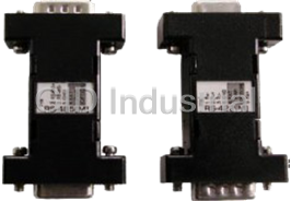
Self powered DB9 RS-232 to DB9 RS-422 Serial Data Converter
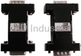
Self powered DB9 RS-232 to DB9 RS-485 Serial Data Converter
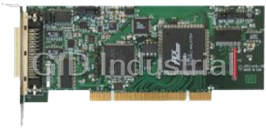
High-Speed, Low-Profile, Universal PCI, 16-bit Multifunction Analog I/O Board
Low Profile single port asynchronous serial communication card that can be installed in any 3.3V or ...
Low Profile Quad-port asynchronous RS-232serial communication card that can be installed in any 3.3V...
Request a Quote

The quote request has been received
Close

Facing challenges or have inquiries? Feel free to contact us!
Call Us +1-469-283-2440
What they say about us
FANTASTIC RESOURCE
One of our top priorities is maintaining our business with precision, and we are constantly looking for affiliates that can help us achieve our goal. With the aid of GID Industrial, our obsolete product management has never been more efficient. They have been a great resource to our company, and have quickly become a go-to supplier on our list!
Bucher Emhart Glass
EXCELLENT SERVICE
With our strict fundamentals and high expectations, we were surprised when we came across GID Industrial and their competitive pricing. When we approached them with our issue, they were incredibly confident in being able to provide us with a seamless solution at the best price for us. GID Industrial quickly understood our needs and provided us with excellent service, as well as fully tested product to ensure what we received would be the right fit for our company.
Fuji
HARD TO FIND A BETTER PROVIDER
Our company provides services to aid in the manufacture of technological products, such as semiconductors and flat panel displays, and often searching for distributors of obsolete product we require can waste time and money. Finding GID Industrial proved to be a great asset to our company, with cost effective solutions and superior knowledge on all of their materials, it’d be hard to find a better provider of obsolete or hard to find products.
Applied Materials
CONSISTENTLY DELIVERS QUALITY SOLUTIONS
Over the years, the equipment used in our company becomes discontinued, but they’re still of great use to us and our customers. Once these products are no longer available through the manufacturer, finding a reliable, quick supplier is a necessity, and luckily for us, GID Industrial has provided the most trustworthy, quality solutions to our obsolete component needs.
Nidec Vamco
TERRIFIC RESOURCE
This company has been a terrific help to us (I work for Trican Well Service) in sourcing the Micron Ram Memory we needed for our Siemens computers. Great service! And great pricing! I know when the product is shipping and when it will arrive, all the way through the ordering process.
Trican Well Service
GO TO SOURCE
When I can't find an obsolete part, I first call GID and they'll come up with my parts every time. Great customer service and follow up as well. Scott emails me from time to time to touch base and see if we're having trouble finding something.....which is often with our 25 yr old equipment.
ConAgra Foods