

 Manufacturers
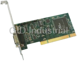
PORTWELL U-RDI-54
Description
Remote rugged 54-bit digital inputs from USB in a NEMA 4 enclosure for harsh environments. Digital voltage inputs up to 50V per channel can be monitored.
Part Number
U-RDI-54
Price
Request Quote
Manufacturer
PORTWELL
Lead Time
Request Quote
Category
I/O Products
Specifications
Categorization Information
IO Products
Features
- Remote Intelligent Digital Input
- Opto-Isolated RS-485 Serial Interface to Host Computer
- 54 Digital Inputs
- Digital Input Voltages up to 50V
- NEMA4 Enclosure for Harsh Atmospheric or Marine Environments
- Type 8031 Microcontroller with 8K RAM and 8K EEPROM. (32K X 8 optional)
- All Programming in Software, No Switches or Jumpers to Set
- 8-Bit Digital Input Software Counters
- Change-of-State Flag Readable via the Serial Port
Datasheet

Extracted Text
Remote Serial Interface Pod RDI-54 User Manual
NOTICES
The information in this document is provided for reference only. Portwell I/O PRODUCTS
INC does not assume any liability arising out of the application or use of the information
or products described herein. This document may contain or reference information and
products protected by copyrights or patents and does not convey any license under the
patent rights of Portwell, nor the rights of others.
Printed in USA. Copyright All rights reserved.
i
Remote Serial Interface Pod RDI-54 User Manual
TABLE OF CONTENTS
INSTALLATION ................................................................ . 1-1
INSTALLING THE SOFTWARE ............................................. . 1-1
INSTALLING THE POD ................................................... . 1-4
PIN CONNECTIONS ..................................................... . 1-3
FUNCTIONAL DESCRIPTION .................................................... . 2-1
FEATURES ............................................................ . 2-1
DESCRIPTION .......................................................... . 2-1
BLOCK DIAGRAM ....................................................... . 2-2
SOFTWARE .................................................................. . 3-1
GENERAL ............................................................. . 3-1
Command Structure ................................................ . 3-1
Addressed Mode .................................................. . 3-1
Non-Addressed Mode ............................................... . 3-2
Command List ................................................... . 3-2
COMMAND FUNCTIONS .................................................. . 3-2
Set Time Base .................................................... . 3-2
Read Digital Inputs ................................................. . 3-3
Read Change-of-State .............................................. . 3-3
Enable Change-of-State Detection ..................................... . 3-4
Selecting Which Edge Will Increment Counter ............................ . 3-5
Read Digital Input Counter ........................................... . 3-5
Reset Counter .................................................... . 3-5
Read Firmware Revision Number ...................................... . 3-6
Resend Last Response .............................................. . 3-6
Hello Message .................................................... . 3-6
Setting a New Baud Rate ............................................ . 3-7
Programming Pod Address ........................................... . 3-8
Entering a New Program ............................................ . 3-8
ERROR CODES: ........................................................ . 3-9
SPECIFICATIONS ............................................................. . 4-1
SERIAL COMMUNICATIONS INTERFACE .................................... . 4-1
DIGITAL INPUTS ........................................................ . 4-1
ENVIRONMENTAL ....................................................... . 4-1
POWER REQUIRED ..................................................... . 4-2
WARRANTY .................................................................. . 5-1
APPLICATION CONSIDERATIONS ................................................ . A-1
ii
Remote Serial Interface Pod RDI-54 User Manual
INSTALLATION
INSTALLING THE SOFTWARE
You have received with your product a CD that contains all the software you need to use
your card. The CD is compatible with any type of Windows or DOS system.
To install the software required for your card:
1. Insert CD in your CD ROM - If the install program does not start within 30
seconds, run “install.exe” from the root directory of the CD.
2. Click the Install Software to Hard Disk button.
3. Select the product you wish to install from the list shown.
4. Click Next.
5. The CD creates a directory with a default name; if you want to change it,
click Change and select the path you prefer.
6. We advise you to also install the Tools Package at least once per system.
7. Click Quick Install to run the install process or click Detailed Install if you
want more information on the files installed.
8. Click Finish.
9. Click Exit install program when finished.
You now have two types of files on your hard disk:
1. Software, including samples in C, Pascal, QuickBasic and a setup program, specifically
for your card.
2. Software to help you use Portwell cards under a variety of environments:
Setup.exe Setup program
Findbase.exe DOS utility to determine an available base address for ISA bus , non-PnP
cards. Run this program once, before the hardware is installed in the
computer, to determine an available address to give the card. Once the
address has been determined, run the setup program provided with the
hardware to see instructions on setting the address switch and various
option selections.
th
Poly.exe A generic utility to convert a table of data into an n order polynomial.
Useful for calculating linearization polynomial coefficients for
1-1
Remote Serial Interface Pod RDI-54 User Manual
thermocouples and other non-linear sensors.
Risc.bat A batch file demonstrating the command line parameters of RISCTerm.exe.
RISCTerm.exe A dumb-terminal type communication program designed for RS422/485
operation. Used primarily with REMOTE Portwell data acquisition Pods
and our RS422/485 serial communication product line. Can be used to say
hello to an installed modem. RISCTerm stands for Really Incredibly Simple
Communications TERMinal
In the ACCES32
directory: This directory contains the Windows 95/98/NT driver used to provide
access to the hardware registers when writing 32-bit Windows software.
Several samples are provided in a variety of languages to demonstrate
how to use this driver. The DLL provides four functions (InPortB,
OutPortB, InPort, and OutPort) to access the hardware.
This directory also contains the device driver for NT. This device driver
provides register-level hardware access from Windows NT, normally called
through ACCES32.DLL. Two methods of using the driver are provided, the
ACCES32.DLL (recommended) and the DeviceIOControl handles direct to
the SYS file (slightly faster)
ACCES95 and ACCESNT
These two drivers are mentioned for users migrating from older versions of
Portwell Tools. The functionality of ACCES95 and ACCESNT has been
combined into ACCES32.DLL, which is described up .
In order to modify your software to use the new ACCES32.DLL, change the
file you link to from ACCES95 or ACCESNT to ACCES32. No other changes
are necessary.
If you want to avoid recompiling software that was written for ACCES95 or
ACCESNT, just rename ACCES32.DLL to the appropriate name (95 or NT).
In the BSAMPLES
directory: A Quickbasic sample.
In the CSAMPLES
directory: Samples in C.
In the PCI
directory: This directory contains PCI-bus specific programs and information. If you
are not using an Portwell PCI card, you can ignore or delete this directory.
In the PSAMPLES
directory: This directory contains samples in Pascal
1-2
Remote Serial Interface Pod RDI-54 User Manual
In the VBACCES
directory: Sixteen-bit DLL drivers for use with VisualBASIC 3.0 and Windows 3.1 only.
These drivers provide four functions, similar to the ACCES32 DLL.
However, this DLL is only compatible with 16-bit executables. Migration
from 16-bit to 32-bit is simplified because of the similarity between
VBACCES and ACCES32.
In the WIN32IRQ
directory: you have utility software to handle IRQs from any card under Win95/98 or
NT
1. Drivers.src with 3 subdirectories
a. DLL Samples for using ACCES32.DLL are provided in this directory.
Using this DLL not only makes the hardware programming easier
(MUCH easier), but also one source file can be used for both
Windows 95/98 and WindowsNT. One executable can run under
both operating systems and still have full access to the hardware
registers. The DLL is used exactly like any other DLL, so it is
compatible with any language capable of using 32-bit DLLs. Consult
the manuals provided with your language’ s compiler for information
on using DLLs in your specific environment.
b. SYS The samples in this directory are provided ONLY for WindowsNT.
The DeviceIOControl based interaction with the register-level driver
is only available in NT. If your code is written to use this method, it
will not work with Windows 95 or Windows 98.
The SYS file is the actual workhorse behind hardware access in
WindowsNT. It utilizes the DeviceIOControl API function for
interaction with user code. Samples are provided demonstrating this
API call, but it is strongly recommended that the DLL interface be
used. The DLL described above encapsulates the SYS file and
performs the DeviceIOControl calls at a small penalty in speed. (A
call through the DLL interface)
c. VXD source fo the driver
2. Samples: Samples in VisualC, Delphi and C++ Builder
1-3
Remote Serial Interface Pod RDI-54 User Manual
INSTALLING THE POD
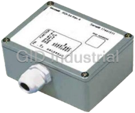
The RDI-54 enclosure is a sealed, die-cast aluminum-alloy NEMA-4 enclosure that can be
easily mounted. Outside dimensions of the enclosure are: 4.53" long by 3.54" wide by
2.17" high. The cover incorporates a recessed neoprene gasket and the cover is secured
to the body by four recessed M-4, stainless steel, captive screws. Two long M-3.5 X 0.236
screws are provided for mounting the body. Mounting holes and cover-attaching screws
are outside the sealed area to prevent ingress of moisture and dust. Four threaded bosses
inside the enclosure provide for mounting the printed circuit card assemblies.
A screw terminal assembly is provided for electrical connections inside the pod. You can
make these connections by assembling a cable of whatever length you need. At the other
end you can either assemble a 62-pin connector to mate with a header on your termination
panel (for ease of connect/disconnect) or whatever termination method best fits your
application.
If you desire, Portwell can provide a custom cable fabricated according to your
specifications.
(Continued on next page)
1-4
Remote Serial Interface Pod RDI-54 User Manual
PIN CONNECTIONS
Connections to RDI-54 are made at a screw terminal assembly located at the top of the
module. Screw terminal numbers silk-screened on that card and the corresponding signals
are as follows:
Term. # Signal Term.# Signal
1 Bit 5 *** 32 Bit 53
2 Bit 4 33 Bit 52
3 Bit 3 34 Bit 6
4 Bit 2 35 Bit 7
5 Bit 33 36 Bit 1
6 Bit 34 37 Bit 0
7 Bit 35 38 Bit 24
8 Bit 39 39 Bit 25
9 Bit 38 40 Bit 26
10 Bit 8 41 Bit 27
11 Bit 9 42 Bit 31
12 Bit 10 43 Bit 30
13 Bit 11 44 Bit 29
14 Bit 13 45 Bit 28
15 Bit 12 46 Bit 32
16 Bit 14 47 Bit 18
17 Bit 15 48 Bit 19
18 Bit 37 49 Bit 20
19 Bit 36 50 Bit 21
20 Bit 40 51 Bit 22
21 Bit 41 52 Bit 23
22 Bit 42 53 Reset
23 Bit 43 54 RS485+
24 Bit 47 55 RS485-
25 Bit 46 56 /INT0
26 Bit 45 57 Local Pwr *
27 Bit 44 58 Local Pwr Gnd
28 Bit 16 59 Isolator Pwr **
29 Bit 17 60 Isolator Pwr Gnd
30 Bit 51 61 Bit 50
31 Bit 48 62 Bit 49
Notes:
* “Local” Power is power from a local power supply. The voltage can be anywhere
from 7.5 VDC to 16 VDC. Higher local power, 24 VDC for example, can be used if
an external zener diode is used to reduce the voltage applied to RDI-54. (Se e
Temperature de-rating comments in the Specification section of this manual under
“Power Required”.)
1-5
Remote Serial Interface Pod RDI-54 User Manual
** “Isolator” Power is used by the opto-isolator section of RDI-54 and should be
independent of “Local Power”. Isolator power should be connected between
terminals 59 and 60. That power can be the computer's +12V supply (via the serial
communications cable) or from an isolated local power supply. The power level can
be from 7.5 to 35 VDC and the isolator section will require only 7 mA of current. If
a separate power supply is not available, then, with loss of some isolation, these
isolator power terminals can be connected to the local power terminals. Regardless
of isolation mode selected via the ISO/ISO jumpers, power must be applied to these
pins for serial communication to function.
*** Digital Inputs are protected by series resistors. There are no onboard pull-up or
pull-down resistors on the inputs. An unconnected input will be a floating logic level
and its state can not be guaranteed.
To ensure that there is minimum susceptibility to EMI and minimum radiation, it is important
that there be a positive chassis ground. Also, proper EMI cabling techniques (cable
connect to chassis ground at the aperture, twisted pair wiring, and, in extreme cases,
ferrite-level of EMI protection) must be used on input/output wiring.
CE-marked versions of RDI-54 meet the requirements of EN50081-1:1992 (Emissions),
EN50082-1:1992 (Immunity), and EN60950:1992 (Safety).
1-6
Remote Serial Interface Pod RDI-54 User Manual
FUNCTIONAL DESCRIPTION
FEATURES
* Opto-Isolated RS-485 Serial Interface to Host Computer.
* 54 Digital Inputs
* Digital Input Voltages up to 50V.
* NEMA4 Enclosure for Harsh Atmospheric or Marine Environments.
* Type 8031 Microcontroller with 8K RAM and 8K EEPROM. (32K X 8
optional)
* All Programming in Software, No Switches or Jumpers to Set.
* 8-Bit Digital Input Software Counters.
* Change of State Flag Readable via the Serial Port.
DESCRIPTION
RDI-54 is an intelligent interface unit that connects up to 54 parallel digital inputs to a
computer. It is packaged in a NEMA4 enclosure for remote installation in harsh
environments. Communication with the host computer is via EIA RS-485 half-duplex, serial
communications protocol. ASCII-based command/response protocol permits communication
with virtually any computer system. RDI-54 is one of a series of remote intelligent units
called the “REMOTE Portwell” series. As many as 31 REMOTE Portwell Series pods (or
other RS-485 devices) may be connected to the computer on a single two-wire multidrop
RS-485 network.
A type 8031 microcontroller (with 8Kx8 RAM, 8Kx8 non-volatile EEPROM, and a watchdog
timer circuit) gives RDI-54 the capability and versatility expected from a modern distributed
control system. To accomodate special programs, the RAM and EEPROM can each be
expanded to 32K x 8. The unit contains CMOS low-power circuitry, an optically-isolated
receiver/transmitter, and power conditioners for local and external isolated power. It can
operate at baud rates up to 57.6 Kbaud at distances up to 5000 feet with low-attenuation
twisted-pair cabling.
All programming of RDI-54 is in ASCII-based software and there are no switches or jumpers
to set. (One exception to the foregoing is that you have the option of by-passing the
optoisolators by re-locating three jumpers.) Use of ASCII-based software permits you to
write applications in any high-level language that supports ASCII string functions and you
can use REMOTE Portwell series modules with virtually any computer.
The module, or pod, address is programmable from 00 to FF hex and whatever address is
assigned is stored in EEPROM and used as the default address at the next Power-ON.
Similarly, the baud rate is programmable for 1200, 2400, 4800, 9600, 14400, 19200, 28800,
and 57600 and is stored in EEPROM and used as default at the next Power-ON.
The time base, used in all time-relevant operations is also software selectable to
2-1
Remote Serial Interface Pod RDI-54 User Manual
provide digital-input sample rates from 14 Hz to 1 KHz
Digital inputs of up to 50V amplitude may be read individually, or in 8-bit bytes. There are
also digital input counters on each input. Selectable edges can be counted for up to 255
transitions. These counters support Read and Reset commands. Moreover, change-of-
state flags can be set on any enabled input bits and can be read via the serial port. This
is particularly useful in applications where it’ s necessary to detect contact closures or
openings. This change-of-state detection capability is enabled on a bit-by-bit basis for all
input bits.
BLOCK DIAGRAM
The built-in watchdog timer resets the pod if, for some unexpected reason, the
microcontroller “hangs up”. Data collected by the pod can be stored in local RAM and
accessed later through the computer's serial port. This facilitates a stand-alone pod mode
of operation.
2-2
Remote Serial Interface Pod RDI-54 User Manual
SOFTWARE
GENERAL
You received ASCII-based software on CD for use with RDI-54. ASCII programming
permits you to write applications in any high level language that supports ASCII string
functions.
The communication protocol has two forms: addressed and non-addressed. Non-
addressed protocol can be used when only one RDI-54 is in use. When more than one
module (pod) is in use, addressed protocol must be used. The only difference is that an
address command is sent to enable the specific pod. The address command is only sent
once during communication between the pod and the host computer. It enables
communication with that specific pod and disables all other pods on the network.
Command Structure
All communication must be 7 data bits, even parity, 1 stop bit. All numbers sent to or
received from the pod are in hexadecimal form. The factory default baud rate is 9600 Baud.
The pod is considered to be in addressed mode any time its pod address is not 00. The
factory default pod address is 00 (non-addressed mode).
Addressed Mode
The address select command must be issued before any other command to the addressed
pod. The address command is as follows:
“!xx[CR]” where xx is the pod address from 01 to FF hex, and [CR] is Carriage
Return, ASCII character 13.
The pod responds with “xxN[CR]” or “xxY[CR]” if an input change of state has occurred on
enabled bits since the last “Y” or address command, or with “xxN[CR]” otherwise.
Once the address select command has been issued, all further commands (other than a
new address select) will be executed by the selected pod. The addressed mode is required
when using more than one pod.
Non-Addressed Mode
When there’ s only one pod connected, no address select command is needed. You can
merely issue commands listed in the following table. Terminology used is as follows:
a. The single lower case letter ‘ x’ designates any valid hex digit (0-F).
b. The single lower case letter ‘ b’ designates either a ‘ 1' or ‘ 0'.
c. The single lower case letter 'p' designates eight-bit port.
3-1
Remote Serial Interface Pod RDI-54 User Manual
d. The symbol ‘ ±’ designates either a ‘ +’ or a ‘ -’ .
e. All commands are terminated with CR, the ASCII character #13.
f. Wherever xx is used to designate a bit number, only 00-35 are valid.
g. All commands are case insensitive; i.e., can be either upper case or lower case
. h. The symbol ‘ *’ means zero or more valid characters (total msg length <255 .
decimal)
Command List
Sxxxx Set a new timebase. 039A
Frequently asked questions
Why choose IPC Station?

What is IPC Station' warranty policy for the U-RDI-54?
What carriers does IPC Station use to ship parts?
Does IPC Station sell to international (non-USA) customers?
What methods of payment does IPC Station accept?
Why buy from GID?

Quality
We are industry veterans who take pride in our work

Protection
Avoid the dangers of risky trading in the gray market

Access
Our network of suppliers is ready and at your disposal

Savings
Maintain legacy systems to prevent costly downtime

Speed
Time is of the essence, and we are respectful of yours
Related Products
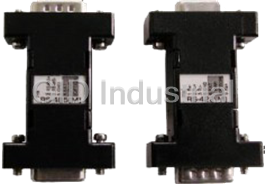
Self powered DB9 RS-232 to DB9 RS-422 Serial Data Converter
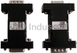
Self powered DB9 RS-232 to DB9 RS-485 Serial Data Converter
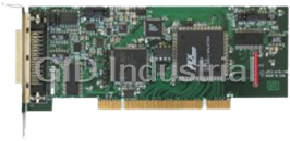
High-Speed, Low-Profile, Universal PCI, 16-bit Multifunction Analog I/O Board
Low Profile single port asynchronous serial communication card that can be installed in any 3.3V or ...
Low Profile Quad-port asynchronous RS-232serial communication card that can be installed in any 3.3V...
Request a Quote

The quote request has been received
Close

Facing challenges or have inquiries? Feel free to contact us!
Call Us +1-469-283-2440
What they say about us
FANTASTIC RESOURCE
One of our top priorities is maintaining our business with precision, and we are constantly looking for affiliates that can help us achieve our goal. With the aid of GID Industrial, our obsolete product management has never been more efficient. They have been a great resource to our company, and have quickly become a go-to supplier on our list!
Bucher Emhart Glass
EXCELLENT SERVICE
With our strict fundamentals and high expectations, we were surprised when we came across GID Industrial and their competitive pricing. When we approached them with our issue, they were incredibly confident in being able to provide us with a seamless solution at the best price for us. GID Industrial quickly understood our needs and provided us with excellent service, as well as fully tested product to ensure what we received would be the right fit for our company.
Fuji
HARD TO FIND A BETTER PROVIDER
Our company provides services to aid in the manufacture of technological products, such as semiconductors and flat panel displays, and often searching for distributors of obsolete product we require can waste time and money. Finding GID Industrial proved to be a great asset to our company, with cost effective solutions and superior knowledge on all of their materials, it’d be hard to find a better provider of obsolete or hard to find products.
Applied Materials
CONSISTENTLY DELIVERS QUALITY SOLUTIONS
Over the years, the equipment used in our company becomes discontinued, but they’re still of great use to us and our customers. Once these products are no longer available through the manufacturer, finding a reliable, quick supplier is a necessity, and luckily for us, GID Industrial has provided the most trustworthy, quality solutions to our obsolete component needs.
Nidec Vamco
TERRIFIC RESOURCE
This company has been a terrific help to us (I work for Trican Well Service) in sourcing the Micron Ram Memory we needed for our Siemens computers. Great service! And great pricing! I know when the product is shipping and when it will arrive, all the way through the ordering process.
Trican Well Service
GO TO SOURCE
When I can't find an obsolete part, I first call GID and they'll come up with my parts every time. Great customer service and follow up as well. Scott emails me from time to time to touch base and see if we're having trouble finding something.....which is often with our 25 yr old equipment.
ConAgra Foods