

 Manufacturers
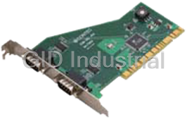
PORTWELL COM-2CL-PCI
Description
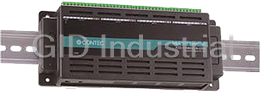
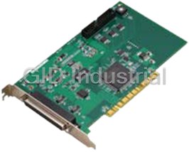
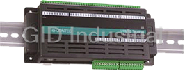
This product is a PCI board expanding a serial communication function of RS-232C conformity to a PC. It carries a RS-232C communication port of 2ch.
Part Number
COM-2CL-PCI
Price
Request Quote
Manufacturer
PORTWELL
Lead Time
Request Quote
Category
Contec I/O Products
Specifications
Categorization Information
Contec I/O Products
Features
- 2ch serial ports of RS-232C conformity is equipped. Setting a baudrate to 15 - 230,400bps is possible.
- It attaches a usable driver library same as a COM port of PC main body in Windows. It supports Win32 API communication function by OS standard and MSComm of Visual Basic.
- One PC can implement a board to 16 pieces at the maximum. By device manager, Setting it to COM1 - COM256 is possible.
- It put a buffer memory of 64byte for exclusive use of the transmission, and for exclusive use of the reception on each channel.
- As optionally, It prepares straight cable(1.8m), cross cable (1.8m), and 9 pin D-SUB connectors for my own cables(A male type or a female type).
Datasheet

Extracted Text
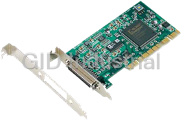
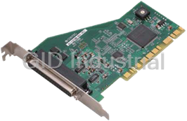
Ver.1.00 PCI-compliant Features 2 port Isolated RS-232C COM-2CL-PCI - 230,400bps (max) RS-232C Serial Communication COM-2CL-PCI – two RS-232C-compliant serial ports. COM-4CL-PCI – four RS-232C-compliant serial ports. Baud rates from 15 to 230,400 bps – user selectable. - Boards can be used as standard serial ports when ® operating in a Windows environment These products come with a driver library that allows the boards ® to be used under Windows in the same way as COM ports on a ® PC. Under Windows , these boards support the OS-standard Win32 API communication function as well as Visual Basic MSComm. The driver library also includes a diagnostic program to confirm hardware operation and to perform communication PCI-compliant tests. 4 port Isolated RS-232C - 16 boards (max) can be installed with an access range COM-4CL-PCI from COM1 to COM256. Up to 16 boards can be installed in a single PC. COM1 - COM256 can be set using the device manager. - Each channel is equipped with separate 64-byte FIFO buffers for transmit and receive. Each individual channel has FIFO buffer memory (transmission: 64 bytes, reception: 64 bytes). This feature is useful for high speed communications and to reduce the load to the CPU during transmitting/receiving. - COM-2CL-PCI uses the same standard 9-pin D-SUB connectors that are used on a PC. This board has a general-purpose RS-232C 9-pin D-SUB connector, allowing you to use standard commercial RS-232C These PCI boards were designed for extending RS-232C cables. compatible serial communication functionality on your PC. COM-2CL-PCI has two RS-232C communication ports. - Available cables and connectors [optional]. COM-4CL-PCI has four RS-232C communication ports. With a 64byte built-in FIFO buffer for transmission and COM-2CL-PCI:Straight cables (1.8m), cross cables (1.8m) and reception of each channel, the product supports a baud ® 9-pin D-SUB connectors (both male and female) for creating your rate of up to 230,400bps. It also comes with a Windows own cables. driver, which allows boards to be used as standard COM ports. COM-4CL-PCI:4 channel distribution cable and 37-pin D-SUB connectors (male) for creating your own cables. - The RS-232C signals can be controlled and monitored via software. Packing List The RTS, CTS, DTR and DSR signals can be controlled and monitored using your software application. - Board (One of the followings) …1 [COM-2CL-PCI, COM-4CL-PCI] - First step guide …1 - COM Setup Disk (CD-ROM *1) …1 - Distribution cable (0.25m) …1 (For COM-4CL-PCI only) *1: The CD-ROM contains the driver software and User’s Guide. COM-2CL-PCI, COM-4CL-PCI 1 Ver.1.00 Specifications Support Software COM-2CL-PCI We recommended that you use CONTEC support software in Item Specification your application and development environment. Number of 2channels channels Standard COM Driver Software “COM Setup Disk” (Included) The purpose of this software is to allow the CONTEC serial Interface type RS-232C ® communication boards to be used under Windows in the same Transfer method Asynchronous serial transfer manner as standard computer COM ports. By installing Baud rate 15 - 230,400bps *1 *2 additional boards, you can use COM ports in the range COM1 - Data length 5, 6, 7, 8 bits COM256. 1, 1.5, 2 stop bits *1 The boards can be used for all types of serial communications Parity check Even, Odd, Non-parity *1 including remote access service (RAS) and uninterruptible power Controller chip 162850 or equivalent supply (UPS) applications. (Each channel has 64-byte receive and ® Under Windows , the serial ports can be accessed using the 64-byte transmit FIFO buffers.) standard Win32 API communication routines (CreateFile( ), Connecting 15m (Typical) WriteFile( ), ReadFile( ), and SetCommState( ), etc.) The serial distance ports are also compatible with Visual Basic communication Interrupt requests 1 level use *3 control (MSComm). Memory address 1024byte boundary Power consumption 5VDC 100mA Operating environment ® ® ® ® ® (max) Operating Systems: Windows Vista , XP , Server 2003 , 2000 Operating 0 - 50°C, You can download the latest software versions from CONTEC’s environment 10 - 90%RH (No condensation) document site (http://www.contec.com/comdrv/). Bus specification PCI (32bit, 33MHz *4) For more details on supported operating systems, applicable Dimensions (mm) 121.69(L) x 88.0(H) languages and new information, please visit CONTEC’s Web site. Connector used 9-pin D-SUB connector, 2031-2-9-P [mfd. by gallant, M(male) type] equivalent Weight 100g *1: These items can be set by software. Physical Dimensions *2: Data transmission at high speed may not be performed normally depending on the environment including the status of external device and cable length. *3: The interrupt signals from individual channels are arranged into a 121.69(L) single interrupt signal and output. *4: This board requires power supply at +5V from an expansion slot (it does not work on a machine with a +3.3V power supply alone). COM-4CL-PCI Item Specification Number of channels 4channels Interface type RS-232C [mm] Transfer method Asynchronous serial transfer The standard outside dimension (L) is the distance from the end of the board Baud rate 15 - 230,400bps *1 *2 to the outer surface of the slot cover. Data length 5, 6, 7, 8 bits 1, 1.5, 2 stop bits *1 Parity check Even, Odd, Non-parity *1 Controller chip 162850 or equivalent (Each channel has 64-byte receive and 64-byte transmit FIFO buffers.) Wiring distance 15m (Typ.) Interrupt requests 1 level use *3 Memory address 1024byte boundary Power consumption 5VDC 120mA (Max.) Operating 0 - 50°C, 10 - 90%RH (No condensation) temperature Bus specification PCI (32bit, 33MHz *4) Dimension (mm) 121.69(l) x 88.0(h) [4.79” x 3.46”] Connector used 37-pin D-SUB connector, 2031-2-37-S [mfd. by Gallant, (female)] or equivalent Weight 130g [4.59oz] *1: These items can be set via software. *2: High speed data transmission is dependent upon the application environment including external device status and wiring distance. *3: Individual channel interrupt signals are arranged into a single interrupt signal before output. *4: This board requires +5V power from the expansion slot (it will not work on a system that only supplies +3.3V). COM-2CL-PCI, COM-4CL-PCI 2 88.0(H) Ver.1.00 Optional Cables, Connectors and Accessories Connection to External Devices Cables & Connectors In addition to connecting directly to the board’s connector, you can also connect external devices via a connection distribution RS-232C Straight Cable – 9pin D-SUB (1.8m) cable or connection distribution unit. :RSS-9M/F -Connecting directly to the port connector RS-232C Cross Cable – 9pin D-SUB (1.8m) -Using a connection distribution cable COM-4CL-PCI :RSC-9F -Using a connection distribution unit COM-4CL-PCI RS-232C Straight Cable – 25pin D-SUB (1.8m) COM-2CL-PCI :RSS-25M/F Connecting directly to the port connector If you are connecting an external device directly with the RS-232C Cross Cable – 25pin D-SUB (1.8m) connector on the board, use one of the optional RS-232C cables. :RSC-25F If you make your own cables, use a CN5-D9F or equivalent connector. RS-232C Connection Conversion Straight Cable – 25pin M to 9pin F (1.8m) Pin Assignment :RSS-25M/9F RS-232C Connection Conversion Straight Cable – Screw nut: UNC#4-40 (inch screw) 25pin F to 9pin M (1.8m) 1 6 :RSS-25F/9M CN1 9 RS-232C Connection Conversion Cross Cable – 5 25pin F to 9pin F (1.8m) :RSC-25F/9F 1 6 CN2 Connection Conversion Cable – 37pin M → 4x 9pin M (250mm) 9 5 :PCE37/9PS - Connector used 2031-2-9-P or equivalent to it [mfd. by gallan, M(male) type] Connection Conversion Cable – 37pin M → 4x 25pin M (250mm) - Applicable connector :PCE37/25PS 17JE-13090-02(D8C) [mfd. by DDK, F(female) type] CN5-D9F (Connector five set) [CONTEC, F(female) type] COM-4ch Board Optional Cable for CCU – 78pin F to 25pin M (2m) :RSS-78M/37M 1 DCD1 Data Carrier Detect Data Set Ready DSR1 6 Set of five 9pin D-SUB (male) connectors :CN5-D9M 2 RxD1 Receive Data Request to Send RTS1 7 Set of five 9pin D-SUB (female) connectors :CN5-D9F 3 TxD1 Transmit Data Clear to Send CTS1 8 Set of five 37pin D-SUB (male) connectors :CN5-D37M 4 DTR1 Data Terminal Ready Ring Indicator RI1 9 5 SG1 Signal Ground Accessories CN1 Connection Conversion Unit for RS-232C – 1 DCD2 Data Carrier Detect 78pin F → 8x 25pin M Data Set Ready DSR2 6 :CCU-78F/25M *1 2 RxD2 Receive Data Request to Send RTS2 7 3 TxD2 Transmit Data Clear to Send CTS2 8 *1: RSS-78M/37M cable is needed when using this unit. 4 DTR2 Data Terminal Ready Ring Indicator RI2 9 5 SG2 Signal Ground *Check CONTEC’s Web site for additional information on these CN2 options. Cable (Option) RS-232C Straight Cable – 9pin D-SUB (1.8m) :RSS-9M/F RS-232C Cross Cable – 9pin D-SUB (1.8m) :RSC-9F COM-2CL-PCI, COM-4CL-PCI 3 Ver.1.00 COM-4CL-PCI When using a COM-4CL-PCI, an alternative to connecting an external device directly to the connector on the board is to use either a connection conversion cable or connection conversion unit. Using a 9-pin D-SUB Connector Distribution Cable Use the bundled distribution cable or CONTEC’s PCE37/9PS (available separately) to distribute the signal through four 9-pin D-SUB male connectors. Use commercially available 9-pin D-SUB cables to connect from the four individual connectors to external devices. Pin assignment - Cable CH1 9-conductor shielded cable Cable length : 250mm SG 1 5 9 RI 1 Conductor size : AWG#28 DTR 1 4 8 CTS 1 TxD 1 3 CH1 - Connector used 7 RTS 1 RxD 1 2 37-pin D-SUB, male connector 6 DSR 1 DCD 1 1 Thumb screw : UNC #4-40 (inch screw) CH2 CH3 CH4 SG 4 5 9 RI 4 DTR 4 4 8 CTS 4 TxD 4 3 CH4 7 RTS 4 RxD 4 2 6 DSR 4 DCD 4 1 - Connector used 9-pin D-SUB, male connector Thumb screw : UNC#4-40 (inch screw) - Applicable connectors 17JE-13090-02(D8C) (mfd. by DDK, Female) Connection distribution cable (Optional) Connection Conversion Cable - 37pin M → 4x 9pin M (250mm) :PCE37/9PS Cable (Optional) RS-232C Straight Cable with 9pin D-SUB (1.8m) :RSS-9M/F RS-232C Cross Cable with 9pin D-SUB (1.8m) :RSC-9F Using a 25-pin D-SUB Connector Distribution Cable Use CONTEC’s PCE37/25PS connection distribution cable (available separately) to distribute the signal through four 25-pin D-SUB male connectors. Use CONTEC’s 25-pin D-SUB cables (or equivalent) to connect from the four individual connectors to external devices. CH1 - Cable 9-conductor shielded cable N.C. 13 Cable length : 250mm 25 N.C. N.C. 12 Conductor size : AWG#28 24 N.C. CH1 N.C. 11 - Connector used 23 N.C. N.C. 10 37-pin D-SUB, male connector 22 RI 1 N.C. 9 Thumb screw : 21 N.C. DCD 1 8 UNC #4-40 (inch screw) 20 DTR 1 CH2 SG1 7 19 N.C. DSR 1 6 18 N.C. CTS 1 5 17 N.C. RTS 1 4 16 N.C. CH3 RxD 1 3 15 N.C. TxD 1 2 14 N.C. FG 1 CH4 - Connector used CH4 25-pin D-SUB, male connector Thumb screw : UNC#4-40 (inch screw) 13 N.C. 25 N.C. - Applicable connectors 12 N.C. 24 N.C. 17JE-13250-02(D8C) N.C. 11 23 N.C. (mfd. by DDK, Female) N.C. 10 22 RI 4 9 N.C. 21 N.C. 8 DCD 4 20 DTR 4 SG 4 7 19 N.C. 6 DSR 4 18 N.C. 5 CTS 4 17 N.C. 4 RTS 4 16 N.C. RxD 4 3 15 N.C. 2 TxD 4 14 N.C. 1 FG Connection distribution cable (Optional) Connection Conversion Cable – 37pin M → 4x 25pin M (250mm) :PCE37/25PS Cables (Optional) RS-232C Straight Cable – 25pin D-SUB (1.8m) :RSS-25M/F RS-232C Cross Cable – 25-pin D-SUB (1.8m) :RSC-25F RS-232C Connection Conversion Straight Cable – 25pin F→ 9pin M (1.8m) :RSS-25F/9M RS-232C Connection Conversion Cross Cable – 25pin F→ 9pin F (1.8m) :RSC-25F/9F COM-2CL-PCI, COM-4CL-PCI 4 . . . . . . . . Ver.1.00 Using a 25-pin D-SUB Connector Distribution Unit Use CONTEC’s CCU-78F/25M connection distribution unit (available separately) to distribute the signal through four 25-pin D-SUB male connectors. Features: - Unit is DIN rail mountable when using CONTEC’s ADP-1 DIN rail adapter (available separately). - Unit can be mounted on a wall or panel. - By connecting to an external power supply, the unit can provide power through the 25-pin D-SUB connector(s). Use CONTEC’s 25-pin D-SUB cables (or equivalent) to connect from the four individual connectors to external devices. RS-232C cables connecting to external devices External device External To Board device Option cable CCU-78F/25M External Connection conversion unit device for the COM-8ch/4ch board 25-pin D-SUB connector 1 FG N.C. 14 2 TxD Transmit Data N.C. 15 3 RxD Receive Data N.C. 16 4 RTS Request to Send N.C. 17 5 CTS Clear to Send N.C. 18 6 DSR Data Set Ready N.C. 19 7 SG Signal Ground Data Terminal Ready DTR 20 8 DCD Data Carrier Detect N.C. 21 9 N.C. Ring Indicator RI 22 10 N.C. N.C. 23 - Connector used 11 N.C. 25-pin D-SUB, male connector N.C. 24 12 N.C. Thumb screw: UNC#4-40 (inch screrw) Power supply output * 25 - Applicable 13 N.C. 17JE-13250-02(D8C) (mfd. by DDK, Female) CN5-D25F (mfd. by CONTEC, Female) (Five connector set) * A power supply output is referred to. Connection distribution cable & connection distribution unit (Optional) Connection Conversion Unit for RS-232C – 78pin F→ 8x 25pin M :CCU-78F/25M 4ch Connection Cable for CCU-78F/25M (2m) :RSS-78M/37M Connection cable (Optional) RS-232C Straight Cable – 25pin D-SUB (1.8m) :RSS-25M/F RS-232C Cross Cable – 25pin D-SUB (1.8m) :RSC-25F RS-232C Connection Conversion Straight Cable – 25pin F→ 9pin M (1.8m) :RSS-25F/9M RS-232C Connection Conversion Cross Cable – 25pin F→ 9pin F (1.8m) :RSC-25F/9F COM-2CL-PCI, COM-4CL-PCI 5 Ver.1.00 Connecting directly to the port connector When connecting an external device directly from the connector on the board, use a CN5-D9F or equivalent connector. Pin Assignment Screw nut: UNC#4-40 (inch screw) 37 19 - Connector used 20 1 37-pin D-SUB, female connector 2031-2-37-S (mfd. by gallant) equivalent - Applicable connector 17JE-23370-02(D8C) (mfd. by DDK, Male) FDCD-37P (mfd. by HIROSE, Male) DC-37P-N (mfd. by JAE, Male) CN5-D37M (mfd. by CONTEC, Male) (Five connector set) 19 TxD1 CH1 Transmit Data 1 CH1 Receive Data 1 RxD1 37 18 RTS1 CH1 Request to Send 1 CH1 Clear to Send 1 CTS1 36 17 DSR1 CH1 Data Set Ready 1 CH1 Signal Ground 1 SG1 35 16 DTR1 CH1 Data Terminal Ready 1 CH1 Data Carrier Detect 1 DCD1 34 15 RI1 CH1 Ring Indicator 1 CH2 Transmit Data 2 TxD2 33 14 RxD2 CH2 Receive Data 2 CH2 Request to Send 2 RTS2 32 13 CTS2 CH2 Clear to Send 2 CH2 Data Set Ready 2 DSR2 31 12 SG2 CH2 Signal Ground 2 CH2 Data Terminal Ready 2 DTR2 30 11 DCD2 CH2 Data Carrier Detect 2 CH2 Ring Indicator 2 RI2 29 10 TxD4 CH4 Transmit Data 4 CH4 Receive Data 4 RxD4 28 9 RTS4 CH4 Request to Send 4 CH4 Clear to Send 4 CTS4 27 8 DSR4 CH4 Data Set Ready 4 CH4 Signal Ground 4 SG4 26 7 DTR4 CH4 Data Terminal Ready 4 CH4 Data Carrier Detect 4 DCD4 25 6 RI4 CH4 Ring Indicator 4 CH3 Transmit Data 3 TxD3 24 5 RxD3 CH3 Receive Data 3 CH3 Request to Send 3 RTS3 23 4 CTS3 CH3 Clear to Send 3 CH3 Data Set Ready 3 DSR3 22 3 SG3 CH3 Signal Ground 3 CH3 Data Terminal Ready 3 DTR3 21 2 DCD3 CH3 Data Carrier Detect 3 CH3 Ring Indicator 3 RI3 20 1 N.C. CN1 COM-2CL-PCI, COM-4CL-PCI 6 Ver.1.00 Types of Cables and Connection Examples RS232C interface cables differ with each connecting device. Please use straight or cross (reverse) type cables depending upon the specifications of the external devices. Example 1 Connection to a Modem (straight cable) TxD TxD (Transmit Data) RxD RxD (Receive Data) RTS RTS (Request to Send) CTS CTS (Clear to Send) DTR DTR (Data Terminal Ready) DSR DSR (Data Set Ready) (Signal Ground) SG SG External device Example 2 Connection to a Computer (cross cable) TxD TxD RxD RxD RTS RTS CTS CTS DTR DTR DSR DSR SG SG External device Example 3 Connection to an External Device TxD TxD RxD RxD RTS RTS CTS CTS DTR DTR DSR DSR SG SG External device COM-2CL-PCI, COM-4CL-PCI 7
Frequently asked questions
Why choose IPC Station?

What is IPC Station' warranty policy for the COM-2CL-PCI?
What carriers does IPC Station use to ship parts?
Does IPC Station sell to international (non-USA) customers?
What methods of payment does IPC Station accept?
Why buy from GID?

Quality
We are industry veterans who take pride in our work

Protection
Avoid the dangers of risky trading in the gray market

Access
Our network of suppliers is ready and at your disposal

Savings
Maintain legacy systems to prevent costly downtime

Speed
Time is of the essence, and we are respectful of yours
Related Products
This product is a PCI bus compatible interface board with high-precision analog input(16-bit,8 ch) a...
Unisolated Analog Input Board for PCI
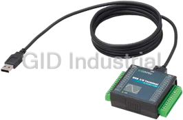
It is an analog input terminal for USB2.0 that an analog measurement is possible by being connected ...
This product is a USB2.0-compliant analog I/O unit that extends the analog I/O function of USB port ...
12-bits Analog I/O Board(Low Gain) for PCI
This product is a USB2.0-compliant analog I/O unit that extends the analog I/O function of USB port ...
Request a Quote

The quote request has been received
Close

Facing challenges or have inquiries? Feel free to contact us!
Call Us +1-469-283-2440
What they say about us
FANTASTIC RESOURCE
One of our top priorities is maintaining our business with precision, and we are constantly looking for affiliates that can help us achieve our goal. With the aid of GID Industrial, our obsolete product management has never been more efficient. They have been a great resource to our company, and have quickly become a go-to supplier on our list!
Bucher Emhart Glass
EXCELLENT SERVICE
With our strict fundamentals and high expectations, we were surprised when we came across GID Industrial and their competitive pricing. When we approached them with our issue, they were incredibly confident in being able to provide us with a seamless solution at the best price for us. GID Industrial quickly understood our needs and provided us with excellent service, as well as fully tested product to ensure what we received would be the right fit for our company.
Fuji
HARD TO FIND A BETTER PROVIDER
Our company provides services to aid in the manufacture of technological products, such as semiconductors and flat panel displays, and often searching for distributors of obsolete product we require can waste time and money. Finding GID Industrial proved to be a great asset to our company, with cost effective solutions and superior knowledge on all of their materials, it’d be hard to find a better provider of obsolete or hard to find products.
Applied Materials
CONSISTENTLY DELIVERS QUALITY SOLUTIONS
Over the years, the equipment used in our company becomes discontinued, but they’re still of great use to us and our customers. Once these products are no longer available through the manufacturer, finding a reliable, quick supplier is a necessity, and luckily for us, GID Industrial has provided the most trustworthy, quality solutions to our obsolete component needs.
Nidec Vamco
TERRIFIC RESOURCE
This company has been a terrific help to us (I work for Trican Well Service) in sourcing the Micron Ram Memory we needed for our Siemens computers. Great service! And great pricing! I know when the product is shipping and when it will arrive, all the way through the ordering process.
Trican Well Service
GO TO SOURCE
When I can't find an obsolete part, I first call GID and they'll come up with my parts every time. Great customer service and follow up as well. Scott emails me from time to time to touch base and see if we're having trouble finding something.....which is often with our 25 yr old equipment.
ConAgra Foods