

 Manufacturers
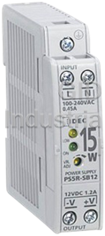
IDEC PS5R-SB24
Description
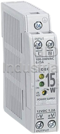
Power Supply, 10/15 Watt, 24VDC, Single Phase, UL508 Listed, Class 1/Div 2, Slim Line Series
Idec PS5R and PS5R-S will be discontinued at the end of 2016, the Idec replacement is the PS5R-V series. The new PS5R-V offers you higher efficiency, smaller size, expanded operating temperature ranges, and longer MTBF. IDEC PS5R and PS5R-S will be discontinued on December 31, 2016. IDEC's PS5R series is UL508 Listed and approved for Class I, Division 2 hazardous locations. With UL508 Listing, you may even be able to use a smaller power supply than you do currently. The outputs that are available in this series are 5VDC, 12VDC or 24VDC, are adjustable +/- 10%, short circuit protected, and regulated to a 2% maximum ripple. Unique spring up terminals allow easy installation of ring lugs, and built in DIN rail clips require no additional brackets. All models have a universal input that accepts 100-240VAC or 110-350VDC. The PS5R is truly a power supply designed with a world market in mind, as evidenced by the UL508 listing, c-UL Listing, TUV approval, and CE marking (EN60950, EN50081-2, and EN50082-2). Our Idec PS5R series is approved for Class I, Division 2. This means flammable gases, vapors or liquid may be present.
Part Number
PS5R-SB24
Price
Request Quote
Manufacturer
IDEC
Lead Time
Request Quote
Category
Power Supplies
Specifications
Part Number
PS5R-SB24
Product Series
PS5R
Weight - lbs.
0.3500
Watts
15 Watt
Voltage
24VDC
Phase
Single Phase
Ratings
Class 1, Division 2, IP20, UL508
Amp Rating
Less Than 5 (See Spec Sheet)
Options
DIN Rail Mount, With LED Light
0)Product Series
PS5R-S Series
Base Unit of Measure
Each
Availability
Standard Stock
Current Output Rating
0.65 Amps
Rated Power
15 Watts
AC Input Voltage Range
85-264 VAC
105-370 VDC
Mounting
Surface Mount
DIN Rail Mount
Protection Ratings
IP20 fingersafe terminals
UL508 Listed - no derating!
UL, c-UL, TIV approved, CE marked
Working Temperature Range
-10°C to 60°C
Dimensions
Height: 3.54 in (90 mm)
Width: 0.89 in (22.5 mm)
Depth: 3.74 in (95 mm)
Categorization Information
Power Supplies
Power Supply, 10/15 Watt, 24VDC, Single Phase,-PS5R-SB24
Features
- "DC ON"indicator light
- Built in PFC on 75W, 120W, and 240W model; compliant with EN61000-3-2
- Eight output capacities
- Fused input, auto-resetting output overcurrent protection
- Long life expectancy - 70,000 hours minimum!
Datasheet

Extracted Text
Switching Power Supplies:
PS5R-V Series
PRODUCT DESCRIPTION
Space saving DIN-rail mount switching
power supplies with global approvals for
both industrial and hazardous locations.
KEY FEATURES
• Compact size preserves panel space
• Slim size (width):
22.5mm (10W/15W/30W)
36mm (60W)
46mm (120W)
STANDARDS COMPLIANCE • Universal Voltage Input:
85-264V AC/100-370V DC
Applicable Standards Mark File No. or Organization
UL508
• Wide operating temperature range
1
UL1310*
ANSI/ISA 12.12.01 UL/c-UL Listed • Spring-up terminals accept ring & fork
CSA C22.2 No.107.1 File No. E467154, E177168
terminals
CSA C22.2 No.213
1
CSA C22.2 No.223*
• Approved for use in Class I Division 2
hazardous locations
TÜV SÜD
EN60950-1
EN50178 • Can be installed in 6 directions
EU Low Voltage Directive,
EN61204-3
EMC Directive
• DIN-rail or panel mount
SEMI F47 — EPRI
• Overcurrent protection with auto-reset
*1: PS5R-VB/VC/VD only
• Meets SEMI F47 Sag Immunity (208V
AC input)
• RoHS compliant
POWER SUPPLY PART NUMBERS
Output Output • Five-year factory warranty
Output Capacity Part Number Input Voltage
Voltage Current
10W PS5R-VB05 5V 2.0A
PS5R-VB12 12V 1.3A
15W
PS5R-VB24 24V 0.65A
100 to 240V AC
PS5R-VC12 12V 2.5A
(Voltage range: 85 to 264V AC /
30W
100 to 370V DC)
PS5R-VC24 24V 1.3A
60W PS5R-VD24 24V 2.5A
120W PS5R-VF24 24V 5.0A
Part Number Structure
PS5R - V
Output Voltage
3
05: 5V*
4
12: 12V*
24: 24V
Output Capacity
B: 10W/15W
*3: PS5R-VB only
C: 30W
*4: PS5R-VB/VC only D: 60W
F: 120W
Note: Use only for interpreting part numbers.
Do not use for developing part numbers.
1
SPECIFICATIONS
5V DC output PS5R-VB05 - - -
Model 12V DC output PS5R-VB12 PS5R-VC12 - -
24V DC output PS5R-VB24 PS5R-VC24 PS5R-VD24 PS5R-VF24
Output Capacity 15W (5V Model is 10W) 30W 60W 120W
Rated Input Voltage 100 to 240V AC
1
(Single-phase two-wire)* (Voltage range: 85 to 264V AC/100 to 370V DC) (Load ≤ 80% at 100-105V DC)
Frequency 50/60 Hz
5V: 0.25A
100V AC 0.7A 1.3A 1.4A
12V, 24V: 0.35A
Input Current (Typ.)
5V: 0.14A
230V AC 0.3A 0.8A 0.7A
12V, 24V: 0.19A
100V AC 18A (Ta = 25°C, cold start)
Inrush Current (Typ.)
230V AC
45A (Ta = 25°C, cold start)
120V AC 0.5mA max.
Leakage Current
230V AC 1.0mA max.
100V AC 5V: 77%, 12V: 82%, 24V: 84% 12V: 83%, 24V: 85% 86% 88%
Efficiency (Typ.)
2
(at rated output)*
230V AC
5V: 73%, 12V: 80%, 24V: 81% 12V: 85%, 24V: 87% 86% 89%
100V AC — — — 0.99
Power Factor (Typ.)
230V AC — — — 0.92
3
Rated Voltage/Current 5V/2.0A* , 12V/1.3A, 24V/0.65A 12V/2.5A, 24V/1.3A 24V/2.5A 24V/5A
Adjustable Voltage Range ±10%
100V AC
5V: 53ms, 12V: 34ms, 24V: 36ms 12V: 13ms, 24V: 15ms 13ms 30ms
Output Holding Time
5V: 330ms
(Typ.)
12V: 110ms
230V AC 12V: 215ms 105ms 33ms
(at rated output)
24V: 110ms
24V: 230ms
Start Time (at rated input and output)
500ms max. 600 ms max. 800 ms max. 700 ms max.
5V, 12V: 200ms max.
Rise Time (at rated input and output) 200ms max.
24V: 250ms max.
Input Fluctuation 0.4% max.
5V: 2.5% max.
Load Fluctuation 1.0% max.
12V, 24V: 1.0% max.
12V: 0.05%/oC max. (-10 to +50oC)
Temperature Change 0.05%/oC max. (-10 to +65oC ) 0.05%/oC max. (-10 to +55oC ) 0.05%/oC max. (-25 to +55oC )
24V: 0.05%/oC max. (-10 to +55oC)
5V: 8% p-p max. (-25 to -10oC)
12V: 6% p-p max. (-25 to -10oC)
12V: 6% p-p max. (-25 to -10oC) 4% p-p max. (-25 to -10oC) 4% p-p max. (-25 to -10oC)
24V: 4% p-p max. (-25 to -10oC)
24V: 4% p-p max. (-25 to -10oC)
5V: 5% p-p max. (-10 to +0oC)
Ripple
12V: 2.5% p-p max. (-10 to +0oC)
12V: 2.5% p-p max. (-10 to +0oC) 1.5% p-p max. (-10 to +0oC) 1.5% p-p max. (-10 to +0oC)
(including noise)
24V: 1.5% p-p max. (-10 to +0oC)
24V: 1.5% p-p max. (-10 to +0oC)
5V: 2.5% p-p max. (0 to +65oC)
12V: 1.5% p-p max. (0 to +50oC)
12V: 1.5% p-p max. (0 to +65oC) 1% p-p max. (0 to +55oC) 1% p-p max. (0 to +55oC)
24V: 1% p-p max. (0 to +55oC)
24V: 1% p-p max. (0 to +65oC)
Overcurrent Protection 105% min. (auto reset)
Operation Indicator
LED (green)
Between input and output terminals: 3,000V AC, 1 minute
Dielectric Strength Between input and ground terminals: 2,000V AC, 1 minute
Between output and ground terminals: 500V AC, 1 minute
Between input and output terminals: 100MΩ min. (500V DC megger)
Insulation Resistance
Between input and ground terminals: 100MΩ min. (500V DC megger)
4
Operating Temperature* –25 to +75°C
–25 to +70°C –25 to +65°C
Operating Humidity 20 to 90% RH (no condensation)
Storage Temperature –25 to +75°C
Storage Humidity 20 to 90% RH (no condensation)
10 to 55Hz, amplitude 0.33mm, 2 hours each
10 to 55Hz, amplitude 0.21mm, 2 hours each in 3
in 3 axes
axes
10 to 55Hz, amplitude 0.375mm, 2 hours each in 3 axes (when used with BNL6 end clips)
Vibration Resistance (when used with BNL6 end clips)
(when used with BNL6 end clips) 10 to 55Hz, amplitude 0.375mm, 2 hours
10 to 55Hz, amplitude 0.375mm, 2 hours each in 3
each in 3 axes (when used with BNL8 end
axes (when used with BNL8 end clips)
clips)
2
Shock Resistance
300 m/s (30G), 3 times each in 6 directions
5
Expected Life* 8 years minimum (at the rated input, 50% load, operating temperature +40°C, standard mounting direction)
EMI EN61204-3 (Class B)
EMC
EMS EN61204-3 (industrial)
UL508 (Listing), UL1310 Class 2 UL508 (Listing)
ANSI/ISA-12.12.01 ANSI/ISA-12.12.01
Safety Standards
CSA C22.2 No. 107.1, 213, 223 CSA C22.2 No. 107.1, 213
EN60950-1, EN50178 EN60950-1, EN50178
Other Standard SEMI F47 (at 208V AC input only)
Degree of Protection IP20 (EN60529)
Dimensions (mm)
90H × 22.5W × 95D 95H × 36W × 108D 115H × 46W × 121D
Weight (approx.) 140g 150g 260g 470g
Terminal Screw M3.5
At normal temperature and humidity unless otherwise specified.
*1: DC input voltage is not subject to safety standards. When using on DC input, connect a fuse to the input terminal for DC input protection.
*2: Under stable state. *3: PS5R-VB05 (5V DC/2.0A) is 10W (Up to 3.0A at Ta = 0 to 40°C. Not subject to safety standards above 2.0A.)
*4: See the output derating curves on page 3.
*5: Calculation of the expected life is based on the actual life of the aluminum electrolytic capacitor. The expected life depends on operating conditions.
2
Output Input
Regulation
CHARACTERISTICS
Operating Temperature vs. Output Current (Derating Curves)
Conditions: Natural air cooling (Operating temperature is the temperature around the switching power supply.)
PS5R-VB05, -VB12, -VB24 PS5R-VC12 PS5R-VC24
100 100 100
Mounting A
Mounting A Mounting A, B
90 90 90
80 80 80
Input Voltage:
Input Voltage: Input Voltage:
70 85-100V AC 70 70
85-100V AC 85-100V AC
60 60 60
50 50 50
Mounting C
40 40 40
30 Mounting B, C, D, E, F 30 30
Mounting B, C, D, E, F
20 20 20 Mounting D, E, F
10 10 10
0 0 0
-30 -20 -10 0 10 20 30 40 50 60 70 80 -30 -20 -10 0 10 20 30 40 50 60 70 80 -30 -20 -10 0 10 20 30 40 50 60 70 80
Operating Temperature (˚C) Operating Temperature (˚C) Operating Temperature (˚C)
Overcurrent Protection Characteristics
PS5R-VD24 PS5R-VF24
100 100
100
Mounting E Mounting C, E
90 90
80 80
Input Voltage:
70 85-100V AC 70
Mounting B, D
Mounting B, C, D
60 60
50 50
40 40
30 Mounting A 30
Mounting A
Mounting F Mounting F
20 20
10 10
0 0
-30 -20 -10 0 10 20 30 40 50 60 70 80 -30 -20 -10 0 10 20 30 40 50 60 70 80
Operating Temperature (˚C) Operating Temperature (˚C)
0
-30
0 100 105 and over
Output Current (%)
Operating Temperature Approved by Safety Standards
UL508, CSA C22.2 No.107.1, ANSI/ISA12.12.01, EN60950-1, EN50178
Part Number
Mounting A Mounting B Mounting C Mounting D Mounting E Mounting F
65 60 60 60 60 60
PS5R-VB05, -VB12, -VB24
PS5R-VC12 50 45 45 45 45 45
PS5R-VC24 55 55 50 45 45 45
55 40 40 40 45 35
PS5R-VD24
55 40 45 40 45 35
PS5R-VF24
Mounting Style
Up
Mounting A Mounting B Mounting C Mounting E Mounting F
Mounting D
(Vertical, standard) (Upright) (Left side up) (Right side up) (Upside down) (Downward)
PS5R-VD/VF
PS5R-VB/VC
Marking Name Description
L N
INPUT L N
INPUT 50/60Hz
INPUT
INPUT 50/60Hz
L, N AC Input Terminal Voltage range: 85 to 264V AC/100 to 370V DC
100-240VAC Ground Terminal Be sure to connect this terminal to a proper ground.
DC ON
100-240VAC
DC ON
+V: Positive output terminal
+V, –V DC Output Terminals
VR. –V: Negative output terminal
ADJ
ON
VR.
Allows adjustment within ±10%.
VR.
ADJ ADJ
ON
VR.ADJ Output Voltage Adjustment Turning clockwise increases the output voltage.
OUTPUT
VR.
ADJ
Turning counterclockwise decreases the output voltage.
-V +V
OUTPUT
DC ON Operation Indicator (green) Illuminates when the output voltage is on.
-V +V
OUTPUT
OUTPUT
3
Output Current (%) Output Current (%)
Output Current (%) Output Current (%)
Output Current (%)
Output Voltage (%)
Intermittent Operation
5-M3.5
95
Screw Terminal
DIMENSIONS (mm)
ACCESSORY PART NUMBERS
44
62.9
12
2
PS5R-VB/VC Panel Mounting Bracket*
24.7
9.5 3.8
22.5
Applicable Switching
2-M4 or 2-M4.5 holes
Part Number Remarks 2-M4 or 2-M4.5 holes
Power Supply
5-M3.5
—
PS9Z-5R1B
PS5R-VB
95
Screw Terminal
PS5R-VC
For side mounting
PS9Z-5R2B
—
PS5R-VD PS9Z-5R1C
5-M3.5
5-M3.5
—
PS5R-VF PS9Z-5R1E
Screw
95
Screw Terminal
10 10 Terminal
108
*2: Used when installing on a panel directly.
DIN Rail (35mm-wide)
5-M3.5
95
Screw Terminal
Length Part Number Material
BNDN1000
1000mm Aluminum
44
62.9
12
End Clip
24.7
9.5 3.8
Part Number
22.5
2-M4 or 2-M4.5 holes
2-M4 or 2-M4.5 holes
44
BNL6
62.9
12
26
24.7
9.5 3.8 BNL8
20
3.8
38
22.5
36
2-M4 or 2-M4.5 holes
2-M4 or 2-M4.5 holes
44
5-M3.5
62.9
12
Screw
2-M4 or 2-ø4.5 holes
Terminal 24.7
10 10 108
PS5R-VD 9.5 3.8
PS5R-VF
22.5
2-M4 or 2-M4.5 holes
2-M4 or 2-M4.5 holes
5-M3.5
5-M3.5
Screw
Screw Terminal
Terminal
10 10 108 11.5 11.5
121
5-M3.5
Screw
5-M3.5
Terminal
10 10 108
95
Screw Terminal
26
20
3.8
38
36
26
2-M4 or 2-ø4.5 holes
20
3.8
38
36
23
5-M3.5
36
44 3.8
2-M4 or 2-ø4.5 holes 46
Screw Terminal
26
62.9 48
12
11.5 11.5
121
20
3.8
38
24.7
9.5 3.8
36
22.5
5-M3.5
2-M4 or 2-M4.5 holes 2-M4 or 2-ø4.5 holes
2-M4 or 2-M4.5 holes
Screw Terminal
2-M4 or 2-ø4.5 holes
11.5 11.5
121
PS9Z-5R2B
PS9Z-5R1B Side-mount - Panel Mounting PS9Z-5R1C Panel Mounting PS9Z-5R1E Panel Mounting
5-M3.5
Panel Mounting Bracket Bracket Bracket Bracket
5-M3.5
Screw Terminal
Screw 11.5 11.5
121
Terminal
10 10 108
5-M3.5
5-M3.5
95
Screw Terminal 95
Screw Terminal
23
36
3.8
46
48
23
2-M4 or 2-ø4.5 holes
36
3.8
46
48
44
44
26
20 62.9
12 62.9
12 3.8
38
36
24.7
24.7 2-M4 or 2-ø4.5 holes
9.5 3.8 23
9.5 3.8
36
3.8
46
22.5
22.5
2-M4 or 2-M4.5 holes
2-M4 or 2-M4.5 holes 2-M4 or 2-M4.5 holes 48
2-M4 or 2-M4.5 holes
2-M4 or 2-ø4.5 holes
2-M4 or 2-ø4.5 holes
5-M3.5
Screw Terminal
5-M3.5
5-M3.5
11.5 11.5
121
Screw
Screw 4
Terminal
10 10 Terminal 108
10 10 108
26
26
20
20
3.8
3.8
38
38
23
36
36
36
3.8
46
48
2-M4 or 2-ø4.5 holes
2-M4 or 2-ø4.5 holes
2-M4 or 2-ø4.5 holes
5-M3.5
5-M3.5
Screw Terminal
Screw Terminal
11.5 11.5
11.5 11.5
121
121
23
23
36
3.8 36
3.8
46
46
48
48
2-M4 or 2-ø4.5 holes
2-M4 or 2-ø4.5 holes
98 8.5
79 8
61.6 12.2 8.2
98 8.5
79 8
61.6 12.2 8.2
90
95
115
90
95
115
4.4 35.3 27.3
4.5 35.3 24.9
4.5 35.3 44.9
4.4 35.3
27.3
4.5 35.3 24.9
98 8.5
4.5 35.3 44.9
98 8.5 79 8
61.6 12.2 8.2
135 79 8
61.6 12.2 8.2
115
125
105 120
98 8.5
79112 8
61.6 12.2 8.2
135
115
125 90
120
105 90
95
112
115
95
115
90
95
115
98 8.5
102
79 8
61.6 12.2 8.2
110
4.4 35.3 27.3
102
4.5 35.3 24.9
4.4 35.3 27.3
4.5 35.3 24.9
110
4.5 35.3 44.9
4.5 35.3 44.9
90
4.4 35.3 27.3
95
4.5 35.3 24.9
115
4.5 35.3 44.9
135
135
115
125
115
125 105 120
105 120
98 8.5
112
79 8
135 112
12.2 8.2
61.6
115
125
105 120
112
90
95
115
4.4 35.3 27.3
4.5 35.3 24.9
4.5 35.3 44.9
102
102
135
110
115
110
125
105 120
102
112
110
4.4 35.3 27.3
4.5 35.3 24.9
4.5 35.3 44.9
135
115
125
120
105
112
102
110
102
110
MTBF*
PS5R-VB: 900,000H minimum
PS5R-VC: 650,000H minimum
MIL-HDBK-217FN2
PS5R-VD: 450,000H minimum
PS5R-VF: 350,000H minimum
*MTBF stands for Mean Time Between Failure, which is calculated according to
statistical device failures, and indicates reliability of a device. It is the statistical
representation of the likelihood of the unit to fail and does not necessarily repre-
sent the expected life of a product.
SAFETY PRECAUTIONS
• Blown fuses indicate that the internal circuits are damaged. Contact IDEC for repair. Do
The PS5R-V should be placed in a proper enclosure. It is designed to be used with general
not just replace the fuse and reoperate, otherwise electric shock, fire, or malfunction
electrical equipment and industrial electric devices.
may occur.
• Do not use the switching power supplies to charge rechargeable batteries.
• Do not use switching power supplies with electric equipment whose malfunction or
• Do not overload or short-circuit the switching power supply for a long period of time,
inadvertent operation may damage the human body or life directly.
otherwise the internal elements may be damaged.
• Make sure that the input voltage and output current do not exceed the ratings. If the
• Do not disassemble, repair, or modify the power supplies, otherwise the high voltage
input voltage and output current exceed the ratings, electric shock, fire, or malfunction
internal part may cause electric shock, fire, or malfunction.
may occur.
• The fuse inside the PS5R-V switching power supply is for AC input. Use an external fuse
• Do not touch the terminals of the switching power supply while input voltage is applied,
for DC input.
otherwise electric shock may occur.
• Provide the final product with protection against malfunction or damage that may be
caused by malfunction of the switching power supply.
• Operating temperatures should not exceed the ratings. Be sure to note the derating
characteristics. If the operating temperature exceeds the ratings, electric shock, fire, or
malfunction may occur.
OPERATING INSTRUCTIONS
Notes for installation
Mounting on DIN Rails
• Do not close the top or bottom openings of the PS5R-V to allow for heat radiation by
1. Use a 35mm-wide DIN rail.
convection.
2.Place the PS5R-V on the DIN rail as shown with input terminal side up ( ), and press the
• When mounting multiple PS5R-V switching power supplies side by side, maintain a
PS5R-V towards the DIN rail ( ). Make sure that the PS5R-V is installed firmly.
minimum of 10 mm clearance. Observe the derating curves in consideration of the
3. Use BNL6 end clips to ensure power supplies do not slide off the end of the DIN rail. Use of
ambient temperature.
BNL8 end clips is recommended when excessive vibration or shock is anticipated.
Removal
• Insert a flat screwdriver into the slot in the clamp, and pull out until it clicks ( ). The lock
mechanism is released and the PS5R-V can be removed ( ). When mounting the PS5R-V
again, push in the latch first.
Mounting Removal
10mm minimum
• When the derating voltage may exceed the recommended value, provide forced air-
cooling.
• Make sure to wire the ground terminal correctly.
• For wiring, use wires of heat resistance of 60oC or higher (PS5R-VB: 80oC or higher). Use
copper wire of the following sizes, according to the rated current.
Clamp
• Recommended wire size: AWG18 to 14
Note: Wires of the above size must be used to comply with UL508, CSA C22.2 No. 107.1.
Applicable crimp terminal (reference)
ø3.6min.
6.6 max.
5.5 min.
4 max.
• Recommended tightening torque of the input and output terminals is 1.0 to 1.3N·m
(0.8N·m for UL).
5
OPERATING INSTRUCTIONS
Installing a Panel Mounting Bracket Overcurrent Protection
The output voltage drops automatically when an overcurrent flows due to an overload or short
Frequently asked questions
Why choose IPC Station?

What is IPC Station' warranty policy for the PS5R-SB24?
What carriers does IPC Station use to ship parts?
Does IPC Station sell to international (non-USA) customers?
What methods of payment does IPC Station accept?
Why buy from GID?

Quality
We are industry veterans who take pride in our work

Protection
Avoid the dangers of risky trading in the gray market

Access
Our network of suppliers is ready and at your disposal

Savings
Maintain legacy systems to prevent costly downtime

Speed
Time is of the essence, and we are respectful of yours
Related Products
Request a Quote

The quote request has been received
Close

Facing challenges or have inquiries? Feel free to contact us!
Call Us +1-469-283-2440
What they say about us
FANTASTIC RESOURCE
One of our top priorities is maintaining our business with precision, and we are constantly looking for affiliates that can help us achieve our goal. With the aid of GID Industrial, our obsolete product management has never been more efficient. They have been a great resource to our company, and have quickly become a go-to supplier on our list!
Bucher Emhart Glass
EXCELLENT SERVICE
With our strict fundamentals and high expectations, we were surprised when we came across GID Industrial and their competitive pricing. When we approached them with our issue, they were incredibly confident in being able to provide us with a seamless solution at the best price for us. GID Industrial quickly understood our needs and provided us with excellent service, as well as fully tested product to ensure what we received would be the right fit for our company.
Fuji
HARD TO FIND A BETTER PROVIDER
Our company provides services to aid in the manufacture of technological products, such as semiconductors and flat panel displays, and often searching for distributors of obsolete product we require can waste time and money. Finding GID Industrial proved to be a great asset to our company, with cost effective solutions and superior knowledge on all of their materials, it’d be hard to find a better provider of obsolete or hard to find products.
Applied Materials
CONSISTENTLY DELIVERS QUALITY SOLUTIONS
Over the years, the equipment used in our company becomes discontinued, but they’re still of great use to us and our customers. Once these products are no longer available through the manufacturer, finding a reliable, quick supplier is a necessity, and luckily for us, GID Industrial has provided the most trustworthy, quality solutions to our obsolete component needs.
Nidec Vamco
TERRIFIC RESOURCE
This company has been a terrific help to us (I work for Trican Well Service) in sourcing the Micron Ram Memory we needed for our Siemens computers. Great service! And great pricing! I know when the product is shipping and when it will arrive, all the way through the ordering process.
Trican Well Service
GO TO SOURCE
When I can't find an obsolete part, I first call GID and they'll come up with my parts every time. Great customer service and follow up as well. Scott emails me from time to time to touch base and see if we're having trouble finding something.....which is often with our 25 yr old equipment.
ConAgra Foods