

 Manufacturers
TRANSCEND TRANSCEND SSD520

Description
Compatible with SATA II 3.0Gb/s standard, due to smaller size, high speed, low power consumption, and great reliability, Transcend's Due to slimmer size, 7mm in height (fit the standard dimensions of 2.5" SATA Hard Disk Drives), low power consumption, SATA Solid State Disk is the perfect storage device for tablet PC, laptop, and industrial PC.
Part Number
TRANSCEND SSD520
Price
Request Quote
Manufacturer
TRANSCEND
Lead Time
Request Quote
Category
Uncategorized
Specifications
Capacity
8GB~32GB
Interface
SATA II
Operating Temperature
0 oC to 70 °C
Storage Temperature
40 oC to 85 °C
Vibration
Operating: 3G(peak-to-peak), 5 - 800Hz
Non-Operating: 5G(peak-to-peak), 5 - 800Hz
Shock
1500 G, 0.5 ms
Max. Power Comsumption
1500 G, 0.5 ms
Dimension
100mm x 70mm x 7mm
Data Rate Transfer
Sequential R/W (MB/sec, max.): 125/85
S.M.A.R.T Support
Yes
Features
- Fully compatible with devices and OS that support the
- SATA II 3.0Gb/s standard.
- Non-Volatile Flash Memory (SLC) for outstanding data retention and reliability
- Global Wear-Leveling and Block management for reliability
- Built-in ECC (Error Correction Code) functionality
- Shock resistance Support
- Security Command
- Ultra-slim
- thickness is only 7mm
- RoHS compliant.
Datasheet

Extracted Text
SSD520 – Features SATA II 3Gb/s SSD • Fully compatible with devices and OS that support the Compatible with SATA II 3.0Gb/s standard, due to SATA II 3.0Gb/s standard. smaller size, high speed, low power consumption, and • Non-Volatile Flash Memory (SLC) for outstanding data great reliability, Transcend’s Due to slimmer size, 7mm retention and reliability. in height (fit the standard dimensions of 2.5’’ SATA Hard • Global Wear-Leveling and Block management for Disk Drives), low power consumption,SATA Solid State reliability. Disk is the perfect storage device for tablet PC, laptop, and industrial PC. • Built-in ECC (Error Correction Code) functionality. • Shock resistance Support. • Security Command. • Ultra-slim, thickness is only 7mm. • RoHS compliant. Specifications Physical Specification Form Factor 2.5 inch HDD Storage Capacities 8GB to 32GB Length 100.00 ± 0.25 mm 3.937 ± 0.01 inch Dimensions Width 69.85 ± 0.25 mm 2.750 ± 0.01 inch Height ± ± 6.8 0.2 mm 0.268 0.008 inch Input Voltage 5V ± 5% Weight 59 ± 2 g Connector SATA 22 pins connector Environmental Specifications o o Operating Temperature 0 C to 70 C o o Storage Temperature − 40 C to 85 C Operating 0 % to 95 % (Non-condensing) Humidity Non-Operating 0 % to 95 % (Non-condensing) Performance ATTO CrystalDiskMark IOmeter Random Random IOPS IOPS Model P/N Max. Max. Sequential Sequential Read Write Random Read Random Write Read Write Read Write (4KB QD32) (4KB QD32) (4KB QD32) (4KB QD32) * * ** ** ** ** *** *** TS8GSSD520 TBD TS16GSSD520 TBD TS32GSSD520 170 85 125 85 15 2.1 4000 440 Note: Maximum transfer speed recorded o ® * 25 C, test on ASUS P8Z68-M PRO, 4 GB, Windows 7 Professional with AHCI mode, benchmark utility ATTO (version 2.41), unit MB/s o ® ** 25 C, test on ASUS P8Z68-M PRO, 4 GB, Windows 7 Professional with AHCI mode, benchmark utility CrystalDiskMark (version 3.0.1), copied file 1000MB, unit MB/s o ® *** 25 C, test on ASUS P8Z68-M PRO, 4 GB, Windows 7 Professional with AHCI mode, benchmark utility IOmeter2006 with 4K file size and queue depth of 32, unit IOPs **** The recorded performance is obtained while the SSD is not operating as an OS disk Actual Capacity Model P/N LBA Cylinder Head Sector TS8GSSD520 15,649,200 15,525 16 63 TS16GSSD520 31,277,232 16,383 16 63 TS32GSSD520 62,533,296 16,383 16 63 Power Requirements o Input Voltage 5V ± 5% @ 25 C Mode P/N / Power Consumption Typical (mA) Max Write* TS8GSSD520 Max Read* TBD Idle* Max Write* TS16GSSD520 Max Read* TBD Idle* Max Write* 353 TS32GSSD520 Max Read* 250 Idle* 73 *Tested with IOmeter running sequential reads/writes and idle mode Reliability Data Reliability Supports BCH ECC 1 bit per 528-byte MTBF 1,000,000 hours 8 GB TBD Endurance (Terabytes Written) 16 GB TBD 32 GB TBD *Tested under JESD218A endurance test method and JESD219A endurance workloads specification. Vibration Operating 3 G (peak-to-peak), 5 - 800 Hz Non-Operating 5 G (peak-to-peak), 5 - 800 Hz * Note: Reference to the IEC 60068-2-6 Testing procedures; Operating-Sine wave, 5-800Hz/1 oct., 1.5mm, 3g, 0.5 hr./axis, total 1.5 hrs. Shock Operating 1500 G, 0.5 ms Non-Operating 1500 G, 0.5 ms * Reference to IEC 60068-2-27 Testing procedures; Operating-Half-sine wave, 1500g, 0.5ms, 3 times/dir., total 18 times. Regulations Compliance TBD Package Dimensions The figure below illustrates the Transcend 2.5” SATA Solid State Drive. All dimensions are in mm. *Note: Tighten mounting screws with no more than 2 Kgf-cm of torque. Pin Assignments Pin No. Pin Name Pin No. Pin Name S1 GND S2 A+ S3 A- S4 GND S5 B- S6 B+ S7 GND P1 NC P2 NC P3 NC P4 GND P5 GND P6 GND P7 5V P8 5V P9 5V P10 GND P11 DAS P12 GND P13 NC P14 NC P15 NC Pin Layout Block Diagram S S S SA A A AT T T TA A A AH H H Hoooosssstttt SATA Interface SSD Controller Flash Interface N N N NA A A AN N N ND D D D N N N NA A A AN N N ND D D D N N N NA A A AN N N ND D D D N N N NA A A AN N N ND D D D F F F Fllllaaaasssshhhh F F F Fllllaaaasssshhhh F F F Fllllaaaasssshhhh F F F Fllllaaaasssshhhh *The quantity of NAND flash varies by capacity. Features Wear-Leveling algorithm The controller supports static/dynamic wear leveling. When the host writes data, the controller will find and use the block with the lowest erase count among the free blocks. This is known as dynamic wear leveling. When the free blocks' erase count is higher than a threshold value plus data blocks', it will activate the static wear leveling, replacing the not so frequently used user blocks with the high erase count free blocks. ECC algorithm Using 66 bit BCH Error Correction Code with each channel, the controller can correct 1 random bit per 528 byte data sector for MLC NAND flash. The hardware executes parity generation and error detection/correction features. Bad-block management When the flash encounters ECC failed, program fail or erase fail, the controller will mark the block as bad block to prevent the used of this block and caused data lost later on. Power Sequence Below figure illustrates the Transcend SSD520 power sequence. 1. Shut down the input power. 2. Power on reset pull low. 3. Wait for the drive to static state. 4. Turn on the input power. 5. Power on to ready pull high. 5V input 90% 500ms 0V 200ms 0.5s Measured from 90% VCC to power on to ready *The actual value may vary depend on device capacity and system environment. ATA Command Register This table with the following paragraphs summarizes the ATA command set. Command Table Support ATA/ATAPI Command Code Protocol General Feature Set EXECUTE DIAGNOSTICS 90h Device diagnostic FLUSH CACHE E7h Non-data IDENTIFY DEVICE ECh PIO data-In READ DMA C8h DMA READ MULTIPLE C4h PIO data-In READ SECTOR(S) 20h PIO data-In READ VERIFY SECTOR(S) 40h or 41h Non-data SET FEATURES EFh Non-data SET MULTIPLE MODE C6h Non-data WRITE DMA CAh DMA WRITE MULTIPLE C5h PIO data-out WRITE SECTOR(S) 30h PIO data-out NOP 00h Non-data READ BUFFER E4h PIO data-In WRITE BUFFER E8h PIO data-out Power Management Feature Set CHECK POWER MODE E5h or 98h Non-data IDLE E3h or 97h Non-data IDLE IMMEDIATE E1h or 95h Non-data SLEEP E6h or 99h Non-data STANDBY E2h or 96h Non-data STANDBY IMMEDIATE E0h or 94h Non-data Security Mode Feature Set SECURITY SET PASSWORD F1h PIO data-out SECURITY UNLOCK F2h PIO data-out SECURITY ERASE PREPARE F3h Non-data SECURITY ERASE UNIT F4h PIO data-out SECURITY FREEZE LOCK F5h Non-data SECURITY DISABLE PASSWORD F6h PIO data-out SMART Feature Set SMART Disable Operations B0h Non-data SMART Enable/Disable Autosave B0h Non-data SMART Enable Operations B0h Non-data SMART Return Status B0h Non-data SMART Execute Off-Line Immediate B0h Non-data SMART Read Data B0h PIO data-In Host Protected Area Feature Set Read Native Max Address F8h Non-data Set Max Address F9h Non-data Set Max Set Password F9h PIO data-out Set Max Lock F9h Non-data Set Max Freeze Lock F9h Non-data Set Max Unlock F9h PIO data-out 48-bit Address Feature Set Flush Cache Ext EAh Non-data Read Sector(s) EXt 24h PIO data-In Read DMA Ext 25h DMA Read Multiple Ext 29h PIO data-In Read Native Max Address Ext 27h Non-data Read Verify Sector(s) Ext 42h Non-data Set Max Address Ext 37h Non-data Write DMA Ext 35h DMA Write DMA FUA Ext 3Dh DMA Write Multiple Ext 39h PIO data-out Write Multiple FUA Ext CEh PIO data-out Write Sector(s) Ext 34h PIO data-out ATA Command Specifications FLUSH CACHE (E7h) This command is used by the host to request the device to flush the write cache. If there is data in the write cache, that data shall be written to the media. The BSY bit shall remain set to one until all data has been successfully written or an error occurs. IDENTIFY DEVICE (ECh) This commands read out 512Bytes of drive parameter information. Parameter Information consists of the arrangement and value as shown in the following table. This command enables the host to receive the Identify Drive Information from the device. READ DMA (C8h) Read data from sectors during Ultra DMA and Multiword DMA transfer. Use the SET FEATURES command to specify the mode value. A sector count of zero requests 256 sectors. READ MULTIPLE (C4h) This command performs similarly to the Read Sectors command. Interrupts are not generated on each sector, but on the transfer of a block which contains the number of sectors defined by a Set Multiple command. READ SECTOR(S) (20h) This command reads 1 to 256 sectors as specified in the Sector Count register from sectors which is set by Sector number register. A sector count of 0 requests 256 sectors. The transfer beings specified in the Sector Number register. READ VERIFY SECTOR(S) (40h/41h) This command verifies one or more sectors on the drive by transferring data from the flash media to the data buffer in the drive and verifying that the ECC is correct. This command is identical to the Read Sectors command, except that DRQ is never set and no data is transferred to the host. SET FEATURES (EFh) This command set parameter to Features register and set drive’s operation. For transfer mode, parameter is set to Sector Count register. This command is used by the host to establish or select certain features. SET MULTIPLE MODE (C6h) This command enables the device to perform READ MULTIPLE and WRITE MULTIPLE operations and establishes the block count for these commands. WRITE DMA (CAh) Write data to sectors during Ultra DMA and Multiword DMA transfer. Use the SET FEATURES command to specify the mode value. WRITE MULTIPLE (C5h) This command is similar to the Write Sectors command. Interrupts are not presented on each sector, but on the transfer of a block which contains the number of sectors defined by Set Multiple command. WRITE SECTOR(S) (30h) Write data to a specified number of sectors (1 to 256, as specified with the Sector Count register) from the specified address. Specify “00h” to write 256 sectors. NOP (00h) The device shall respond with command aborted. For devices implementing the Overlapped feature set, subcommand code 00h in the Features register shall abort any outstanding queue. Subcommand codes 01h through FFh in the Features register shall not affect the status of any outstanding queue. READ BUFFER (E4h) The READ BUFFER command enables the host to read a 512-byte block of data. WRITE BUFFER (E8h) This command enables the host to write the contents of one 512-byte block of data to the device’s buffer. Power Management Feature Set CHECK POWER MODE (E5h or 98h) The host can use this command to determine the current power management mode. IDLE (E3h or 97h) This command causes the device to set BSY, enter the Idle mode, clear BSY and generate an interrupt. If sector count is non-zero, the automatic power down mode is enabled. If the sector count is zero, the automatic power mode is disabled. IDLE IMMEDIATE (E1h or 95h) This command causes the device to set BSY, enter the Idle(Read) mode, clear BSY and generate an interrupt. SLEEP (E6h or 99h) This command causes the device to set BSY, enter the Sleep mode, clear BSY and generate an interrupt. STANDBY (E2h or 96h) This command causes the device to set BSY, enter the Sleep mode (which corresponds to the ATA “Standby” Mode), clear BSY and return the interrupt immediately. STANDBY IMMEDIATE (E0h or 94h) This command causes the drive to set BSY, enter the Sleep mode (which corresponds to the ATA “Standby” Mode), clear BSY and return the interrupt immediately. Security Mode Feature Set SECURITY SET PASSWORD (F1h) This command set user password or master password. The host outputs sector data with PIO data-out protocol to indicate the information defined in the following table. Security set Password data content1 Word Content 0 Control word Bit 0 Identifier 0=set user password 1=set master password Bits 1-7 Reserved Bit 8 Security level 0=High 1=Maximum Bits 9-15 Reserved 1-16 Password (32 bytes) 17-255 Reserved SECURITY UNLOCK (F2h) This command disables LOCKED MODE of the device. This command transfers 512 bytes of data from the host with PIO data-out protocol. The following table defines the content of this information Security Unlock information2 Word Content 0 Control word Bit 0 Identifier 0=compare user password 1=compare master password Bits 1-15 Reserved 1-16 Password (32 bytes) 17-255 Reserved SECURITY DISABLE PASSWORD (F6h) Disables any previously set user password and cancels the lock. The host transfers 512 bytes of data, as shown in the following table, to the drive. The transferred data contains a user or master password, which the drive compares with the saved password. If they match, the drive cancels the lock. The master password is still saved. It is re-enabled by issuing the SECURITY SET PASSWORD command to re-set a user password. SECURITY ERASE PREPARE (F3h) This command shall be issued immediately before the Security Erase Unit command to enable erasing and unlocking. This command prevents accidental loss of data on the drive. SECURITY ERASE UNIT (F4h) The host uses this command to transfer 512 bytes of data, as shown in the following table, to the drive. The transferred data contains a user or master password, which the drive compares with the saved password. If they match, the drive deletes user data, disables the user password, and cancels the lock. The master password is still saved. It is re-enabled by issuing the SECURITY SET PASSWORD command to re-set a user password. SECURITY FREEZE LOCK (F5h) Causes the drive to enter Frozen mode. Once this command has been executed, the following commands to update a lock result in the Aborted Command error: • SECURITY SET PASSWORD • SECURITY UNLOCK • SECURITY DISABLE PASSWORD • SECURITY ERASE PREPARE • SECURITY ERASE UNIT The drive exits from Frozen mode upon a power-off or hard reset. If the SECURITY FREEZE LOCK command is issued when the drive is placed in Frozen mode, the drive executes the command, staying in Frozen mode. Identify Device Information Default Value Word Default Total Data Field Type Information Address Value Bytes 0 044Ah 2 General configuration 1 3FFFh 2 Obsolete 2 C837h 2 Specific configuration 3 0010h 2 Obsolete 4 0000h 2 Retired 5 0240h 2 Retired 6 003Fh 2 Obsolete 7 03BAh 2 Reserved for CFA 8 2EB0h 2 Reserved for CFA 9 0000h 2 Retired 10-19 XXXXh 20 Serial number in ASCII (Right Justified) 20 0002h 2 Retired 21 0002h 2 Retired 22 0000h 2 Obsolete 23-26 XXXXh 8 Firmware revision in ASCII. Big Endian Byte Order in Word 27-46 XXXXh 40 Model number in ASCII (Left Justified) Big Endian Byte Order in Word 47 8001h 2 Number of sectors on Read/Write Multiple command 48 0000h 2 Trusted Computing feature set options 49 0F00h 2 Capabilities 50 4000h 2 Capabilities 51 0200h 2 Obsolete 52 0000h 2 Obsolete 53 0007h 2 Field validity 54 3FFFh 2 Obsolete 55 0010h 2 Obsolete 56 003Fh 2 Obsolete 57 00FBh 2 Obsolete 58 FC10h 2 Obsolete 59 0100h 2 Multiple sector setting 60 XXXXh 2 Total number of user addressable logical sectors for 28-bit command 61 XXXXh 2 Total number of user addressable logical sectors for 28-bit command 62 0000h 2 Obsolete 63 0007h 2 Multiword DMA transfer. Supports MDMA Mode 0,1,and 2 64 0003h 2 Advanced PIO modes supported Minimum Multiword DMA transfer cycle time per word. In PC Card modes this value 65 0078h 2 shall be 0h Recommended Multiword DMA transfer cycle time. In PC Card modes this value 66 0078h 2 shall be 0h 67 0078h 2 Minimum PIO transfer cycle time without flow control 68 0078h 2 Minimum PIO transfer cycle time with IORDY flow control 69 0000h 2 Reserved 70-74 0000h 10 Reserved 75 0000h 2 Queue depth 76 0006h 2 Serial ATA capacities 77 0002h 2 Reserved for future Serial ATA definition 78 0008h 2 Serial ATA features supported 79 0000h 2 Serial ATA features enabled 80 01FCh 2 Major version number (ATA8-ACS) 81 0000h 2 Minor version number 82 7429h 2 Command sets supported 0 83 7D00h 2 Command sets supported 1 84 4002h 2 Command sets supported 2 85-87 XXXXh 6 Features/command sets enabled 88 407Fh 2 Ultra DMA Mode Supported and Selected 89 0000h 2 Time required for Security erase unit completion 90 0000h 2 Time required for Enhanced security erase unit completion 91 0000h 2 Current Advanced power management value 92 0000h 2 Master Password Revision Code 93 0000h 2 Hardware reset result 94 0000h 2 Current automatic acoustic management value 95 0000h 2 Stream Minimum Request Size 96 0000h 2 Streaming Transfer Time - DMA 97 0000h 2 Streaming Access Latency - DMA and PIO 98-99 0000h 2 Streaming Performance Granularity(DWord) 100-103 XXXXh 8 Total number of user addressable logical sectors for 48-bit commands (QWord) 104 0000h 2 Streaming Transfer Time - PIO Maximum number of 512-byte data blocks of LBA Range Entries per DATA SET 105 0001h 2 MANAGEMENT command 106 0000h 2 Physical sector size / logical sector size 107 0000h 2 Inter-seek delay for ISO 7779 standard acoustic testing 108-111 0000h 8 World wide name 112-115 0000h 8 Reserved 116 0000h 2 Reserved for TLC 117-118 0000h 4 Logical Sector size(Dword) 119 0000h 2 Command and feature sets supports 120 0000h 2 Commands and feature sets supported and enabled settings 121-126 0000h 12 Reserved for expanded supported and enabled settings 127 0000h 2 Obselete 128 0000h 2 Security status 129-159 XXXXh 62 Vendor specific 160 0000h 2 CFA Power mode 161-167 0000h 14 Reserved for CFA 168 0000h 2 Reserved 169 0001h 2 Data Set Management is Supported 170-173 0000h 8 Additional Product Identifier (ATA String) 174-175 0000h 4 Reserved 176-205 0000h 60 Current media serial number (ATA String) 206 0000h 2 SCT Command Transport 207-208 0000h 4 Reserved for CE-ATA 209 0000h 2 Alignment of logical blocks within a physical block 210-211 0000h 4 Wrute-Read-Verify Sector Count mode 3 212-213 0000h 4 Wrute-Read-Verify Sector Count mode 2 214-216 0000h 6 Obsolete 217 0001h 2 Nominal media rotation rate 218 0000h 2 Reserved 219 0000h 2 Obsolete 220-255 0000h 72 Reserved SMART Command Support Value Command Value Command D0h Read Data D5h Reserved D1h Read Attribute Threshold D6h Reserved D2h Enable/Disable Autosave D8h Enable SMART Operations D3h Save Attribute Values D9h Disable SMART Operations D4h Execute OFF-Line Immediate DAh Return Status If the reserved size is below a threshold, status can be read from the Cylinder Register using the Return Status command (DAh). SMART DATA Structure BYTE F / V Description 0-1 X Revision code 2-361 X Vendor specific 362 V Off-line data collection status 363 X Self-test execution status byte 364-365 V Total time in seconds to complete off-line data collection activity 366 X Vendor specific 367 F Off-line data collection capability 368-369 F SMART capability Error logging capability 7-1 Reserved 370 F 0 1=Device error logging supported 371 X Vendor specific 372 F Short self-test routine recommended polling time (in minutes) 373 F Extended self-test routine recommended polling time (in minutes) 374 F Conveyance self-test routine recommended polling time (in minutes) 375-385 R Reserved 386-395 F Firmware Version/Date Code 396-397 F Reserved 398-399 F Reserved 400-406 F ‘SMI2244LT’ 407-415 X Vendor specific 416 F Reserved 417 F Program/write the strong page only 418-419 V Number of spare block 420-423 V Average Erase Count 424-510 X Vendor specific 511 V Data structure checksum F=the content of the byte is fixed and does not change. V=the content of the byte is variable and may change depending on the state of the device or the commands executed by the device. X=the content of the byte is vendor specific and may be fixed or variable. R=the content of the byte is reserved and shall be zero. * 4 Byte value : [MSB] [2] [1] [LSB] SMARTAttributes Attribute ID Raw Attribute Value Attribute Name (hex) 01 MSB 00 00 00 00 00 Read Error Rate 05 LSB MSB 00 00 00 00 Reallocated sectors count 09 LSB MSB 00 00 00 00 Reserved 0C LSB MSB 00 00 00 00 Power Cycle Count Uncorrectable sectors count when A0 LSB MSB 00 00 read/write A1 LSB MSB 00 00 00 00 Number of valid spare blocks A2 LSB MSB 00 00 00 00 Number of Child pair A3 LSB MSB 00 00 00 00 Number of initial invalid blocks A4 LSB MSB 00 00 Total erase count A5 LSB MSB 00 00 Maximum erase count A6 LSB MSB 00 00 Minimum erase count A7 LSB MSB 00 00 Average erase count C0 LSB MSB 00 00 Power-off retract Count C2 MSB 00 00 00 00 00 Controlled temperature C3 LSB MSB 00 00 Hardware ECC recovered C4 LSB MSB 00 00 Reallocation event count C6 LSB MSB 00 00 Reserved C7 LSB MSB 00 00 00 00 UltraDMA CRC Error Count Total LBA written (each write unit = F1 LSB MSB 00 00 32MB) Total LBA read (each read unit = F2 LSB MSB 00 00 32MB) Ordering Information TS XG SSD 5 20 Controller SMI2244Lt Transcend Product 5 = SLC Capacity 8 GB to 32 GB 2.5” Solid State Drive The technical information above is based on industry standard data and has been tested to be reliable. However, Transcend makes no warranty, either expressed or implied, as to its accuracy and assumes no liability in connection with the use of this product. Transcend reserves the right to make changes to the specifications at any time without prior notice. CHINA Shanghai: E-mail: sales-cn@transcendchina.com Beijing: E-mail: sales-cn@transcendchina.com Shenzhen: E-mail:sales-cn@transcendchina.com http://cn.transcend-info.com TAIWAN GERMANY No.70, XingZhong Rd., NeiHu Dist., Taipei, Taiwan, R.O.C E-mail:vertrieb-de@transcend-info.com TEL +886-2-2792-8000 http://de.transcend-info.com Fax +886-2-2793-2222 HONG KONG E-mail: sales-tw@transcend-info.com E-mail: sales-hk@transcend-info.com http://tw.transcend-info.com http://hk.transcend-info.com USA JAPAN Los Angeles: E-mail: sales-jp@transcend-info.com E-mail:sales-us@transcend-info.com http://jp.transcend-info.com Maryland: THE NETHERLANDS E-mail:sales-us@transcend-info.com E-mail: sales-nl@transcend-info.com Florida: http://nl.transcend-info.com E-mail:sales-us@transcend-info.com United Kingdom Silicon Valley: E-mail: sales-uk@transcend-info.com E-mail:sales-us@transcend-info.com http://uk.transcend-info.com http://www.transcend-info.com KOREA E-mail: sales-kr@transcend-info.com http://kr.transcend-info.com Revision History Version Date Modification Content 0.1 2015/09/21 Initial release
Frequently asked questions
Why choose IPC Station?

What is IPC Station' warranty policy for the TRANSCEND SSD520?
What carriers does IPC Station use to ship parts?
Does IPC Station sell to international (non-USA) customers?
What methods of payment does IPC Station accept?
Why buy from GID?

Quality
We are industry veterans who take pride in our work

Protection
Avoid the dangers of risky trading in the gray market

Access
Our network of suppliers is ready and at your disposal

Savings
Maintain legacy systems to prevent costly downtime

Speed
Time is of the essence, and we are respectful of yours
Related Products
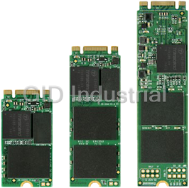
Transcend MTS Series with the next generation SATA III 6Gb/s interface and ultra compact dimensions ...
Transcend's next-generation SATA III 6Gb/s solid state drives deliver significantly improved perform...
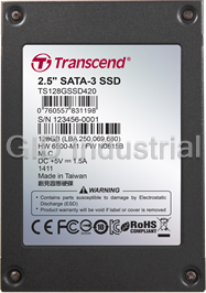
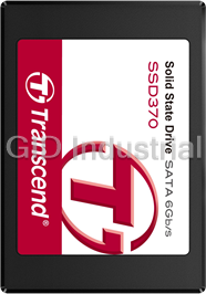
Featuring the latest SATA III 6Gb/s interface and a powerful controller, Transcend SSD420K/SSD420I a...
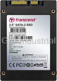
Transcend's 2.5" SATA SSDs provide excellent shock resistance, long term data storage, speedier data...
To meet the demands of industrial grade specifications and ensure the utmost level of quality, Trans...
Request a Quote

The quote request has been received
Close

Facing challenges or have inquiries? Feel free to contact us!
Call Us +1-469-283-2440
What they say about us
FANTASTIC RESOURCE
One of our top priorities is maintaining our business with precision, and we are constantly looking for affiliates that can help us achieve our goal. With the aid of GID Industrial, our obsolete product management has never been more efficient. They have been a great resource to our company, and have quickly become a go-to supplier on our list!
Bucher Emhart Glass
EXCELLENT SERVICE
With our strict fundamentals and high expectations, we were surprised when we came across GID Industrial and their competitive pricing. When we approached them with our issue, they were incredibly confident in being able to provide us with a seamless solution at the best price for us. GID Industrial quickly understood our needs and provided us with excellent service, as well as fully tested product to ensure what we received would be the right fit for our company.
Fuji
HARD TO FIND A BETTER PROVIDER
Our company provides services to aid in the manufacture of technological products, such as semiconductors and flat panel displays, and often searching for distributors of obsolete product we require can waste time and money. Finding GID Industrial proved to be a great asset to our company, with cost effective solutions and superior knowledge on all of their materials, it’d be hard to find a better provider of obsolete or hard to find products.
Applied Materials
CONSISTENTLY DELIVERS QUALITY SOLUTIONS
Over the years, the equipment used in our company becomes discontinued, but they’re still of great use to us and our customers. Once these products are no longer available through the manufacturer, finding a reliable, quick supplier is a necessity, and luckily for us, GID Industrial has provided the most trustworthy, quality solutions to our obsolete component needs.
Nidec Vamco
TERRIFIC RESOURCE
This company has been a terrific help to us (I work for Trican Well Service) in sourcing the Micron Ram Memory we needed for our Siemens computers. Great service! And great pricing! I know when the product is shipping and when it will arrive, all the way through the ordering process.
Trican Well Service
GO TO SOURCE
When I can't find an obsolete part, I first call GID and they'll come up with my parts every time. Great customer service and follow up as well. Scott emails me from time to time to touch base and see if we're having trouble finding something.....which is often with our 25 yr old equipment.
ConAgra Foods