

 Manufacturers
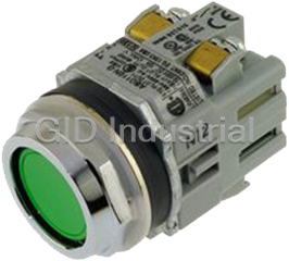
IDEC AL6M-A24-G
Description
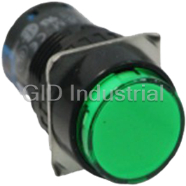
Pushbutton, 16mm, Round, Maintained, 24V, Illuminated, SPDT, IP40, Green
Pushbutton, 16mm, Round, Maintained, Green, DPDT, 24V, IP40
Part Number
AL6M-A24-G
Price
Request Quote
Manufacturer
IDEC
Lead Time
Request Quote
Category
Pushbuttons & E-Stops » Pushbuttons
Specifications
Part Number
AL6M-A24-G
Product Series
AL6
Size
16mm
Normally Open or Closed
2NO/2NC
Ratings
IP40
Weight - lbs.
0.2500
Base Unit of Measure
Each
Categorization Information
Pushbuttons & E-Stops
Pushbutton, 16mm, Round, Maintained, 24V, -AL6M-A24-G
Features
- Super bright LED Illumination
- Momentary, Maintained, Selector, Key, Pilot Light and Push-Lock/Turn-Reset Functions
- Gold-clad silver snap acting contacts for reliable low level switching
- IP40 (dustproof) or IP65 (oiltight) versions
- .110" solder/quick connect termination
- UL Recognized, CSA Certified
Datasheet

Extracted Text
TOP 16mm A6 Switches & Pilot Devices Dimensions (mm) Pushbuttons, Ø 5/8” (16mm) Rubber Gasket Panel Thickness 0.5 to 6 Terminal Width 2.8×0.5t Anti-rotation Ring ş18 Round 2.5 3 Rectangular Square Locking Ring ( ) TOP (TOP) ( ) TOP 1 0.6 5.7 24 18 822 9 9 Oversize Lens Rubber Gasket Anti-rotation Ring Panel Thickness 0.5 to 6 Teminal Width 2.8×0.5t Rectangular Square Round Locking Ring ( ) ( ) (TOP) 2.5 3 TOP TOP 6 6 1 0.6 9 23.5 0.6 9 0.6 8 22 15.5 15.5 12.5 Selector Switches, Ø 5/8” (16mm) Rubber Gasket Panel Thickness 0.5 to 6 Terminal Width 2.8×0.5t Anti-rotation Ring Rectangular Square Round 2.5 3 (TOP) (TOP) (TOP) Locking Ring 8 1 8 22 15.5 24 c18 Key Selector Switches, Ø 5/8” (16mm) Right Contact Left Contact Rubber Gasket Anti-rotation Ring Rectangular Square Round Panel Thickness 0.5 to 6 Terminal Width 2.8×0.5t ( ) ( ) ( ) TOP TOP TOP Locking Ring 2.5 3 N C N O C 1 18 822 26 24 ø18 468 www.idec.com ø18 Circuit Breakers Terminal Blocks Timers Relays & Sockets Display Lights Switches & Pilot Lights 5 5 5 5 5 5 5 5 3 2.5 17.5 18 c 23.5 18 18 ø23.5 Circuit Breakers Switches & Pilot Lights Display Lights Relays & Sockets Timers Terminal Blocks R22 R22 16mm A6 Switches & Pilot Devices Switch Guard, Ø 5/8” (16mm) Panel Thickness 34 0.5 to 5 Panel Thickness 32 0.5 to 5 18 24 Rubber Gasket Rubber Gasket 14 28 14 28 ( ( 90°/110° opening type) 180° opening type) 19 minimum 25 minimum Panel Thickness 34 0.5 to 5 Waterproof Gasket 18 24 for Switch Guard Rubber Gasket 0.4 14 28 19 min. 25 min. Flush Bezel Flush Bezel with Switch Mounting Flush Panel Thickness 0.5 to 5 Bracket Gasket Bezel Plastic Metal Round 1 0.9 0.8 8 29 2 9.8 8.5 2 Square Selector Switches Illuminated & 8.5 2 Non-illuminated Key Lever Rectangular 2 2 2 24 8.5 18.1 17 30 9.3 2 Flush Bezel Mounting Hole Layout Round Square Rectangular +0.2 +0.2 20.2 26.2 – 0.1 – 0.1 30 min.∗ 24 min.∗ 24 min.∗ USA: 800-262-IDEC Canada: 888-317-IDEC 469 ş18 ş18 +0.2 ş20.2 – 0.1 ş24 ş24 23.5 23.5 24 min.∗ 10.5 13 10.5 13 22.6 23 26.5 minimum 45.5 min. (45.5 minimum for 180° opening type) 27.4 21.4 21.4 ş21.4 23.5 23.5 10.5 13 10.5 13 24 min.∗ 26 20 20 ş 20 24 24 18 18 45.5 min. 26.5 minimum (45.5 minimum for 180° opening type) 14.8 33 +0.2 20.2 -0.1 33 24 min.∗ 1 OD 16mm A6 Switches & Pilot Devices Terminal Sockets +0.3 Terminal 1.5×0.3t 8-1.6 0 Holes TOP 33.5 2.5 3 33.5 2.5 3 ( ) TOP NC1 NC2 NO1 NO2 C1 C2 16.2 7.5 66 16.2 3.8 66 Lamp Lamp Terminal (+) Terminal ( ) – PC Board Solder Terminal Type PC Board Terminal Type Terminal Arrangement Mounting Hole Layout ( ) ( ) AL-C6 AL-C6V (Bottom View) (Bottom View) Dust Covers Panel Cut-Outs For Units w/Dust Cover AL-D6, Round AL-DQ6, Square AL-DH6, Rectangular Round/Square Rectangular +0.2 +0.2 c 30 ø24 24 ø16.2 0 ø16.2 0 30 min. 24 min. Waterproof Gasket Waterproof Gasket Waterproof Gasket for Dust Cover for Dust Cover for Dust Cover Marking Plates Pushbuttons with Standard Size Lens Pushbuttons with Oversize Lens Style Round—AL6M-W Square—AL6Q-W Rectangular—AL6H-W Style Round—AL6M-MW Square/Rectangular—AL6Q-QW 2 OD şa şOD Engraving Marking Engraving ❏OD ❏a Area Area Area Dimensions şa ca 2 Dimensions a Marking Marking Area Area Ø 5/8” (16mm) Outside (OD) Ø 0.491” (12.6mm) 0.491” (12.6mm) 1 2 (OD x OD ) 13.8 x Marking Area Outside (OD) (13.8mm) (13.8mm) Ø 0.429” (11mm) 0.429” (11mm) 19.8mm (a) Marking Area 1 2 (12mm) (12mm) (a xa ) 12 x 18mm (a) Engraving must be made on the engraving area within 0.02” (0.5mm) deep. Replacing & and Marking Plate Removal Installation Remove the lens holder assembly (lens, marking plate and holder) from the opera- For illuminated pushbuttons: tor by holding the color lens recesses with the lens removal tool (Part No.MT-101) 1. Insert marking plate inside lens in correct direction and pulling out. Remove marking plate by pushing the color lens from the rear to 2. Press color lens on to lens holder to engage latches. disengage the latches. Marking plate must be engraved on the side as shown in 3. Insert lens holder into housing in correct direction. Do not loosen spring on illuminated pushbutton units (except on pilot light units). The the fi gure on the right. marking plate must be engraved on the front side as shown above. Ø 5/8” (16mm) Fitting Grooves Grooves Engraving Surface Color Lens Marking Plate Lens Holder 470 www.idec.com Circuit Breakers Terminal Blocks Timers Relays & Sockets Display Lights Switches & Pilot Lights 0.3 13 7.5 0.8 şOD 2.4 0.3 13 7.5 0.8 şOD 5 5 1 0.8 a 0.3 13 7.5 24 24 min. 5 5 24 min.
Frequently asked questions
Why choose IPC Station?

What is IPC Station' warranty policy for the AL6M-A24-G?
What carriers does IPC Station use to ship parts?
Does IPC Station sell to international (non-USA) customers?
What methods of payment does IPC Station accept?
Why buy from GID?

Quality
We are industry veterans who take pride in our work

Protection
Avoid the dangers of risky trading in the gray market

Access
Our network of suppliers is ready and at your disposal

Savings
Maintain legacy systems to prevent costly downtime

Speed
Time is of the essence, and we are respectful of yours
Related Products
Pushbutton, 30mm, Momentary, B/G/R, 1NC, Flush, Non-Illuminated, IP65 Our IDEC ABD series are 30mm n...
Pushbutton, 30mm, Momentary, B/G/R, 1NC, Flush, Non-Illuminated, IP65 Our IDEC ABD series are 30mm n...
Request a Quote

The quote request has been received
Close

Facing challenges or have inquiries? Feel free to contact us!
Call Us +1-469-283-2440
What they say about us
FANTASTIC RESOURCE
One of our top priorities is maintaining our business with precision, and we are constantly looking for affiliates that can help us achieve our goal. With the aid of GID Industrial, our obsolete product management has never been more efficient. They have been a great resource to our company, and have quickly become a go-to supplier on our list!
Bucher Emhart Glass
EXCELLENT SERVICE
With our strict fundamentals and high expectations, we were surprised when we came across GID Industrial and their competitive pricing. When we approached them with our issue, they were incredibly confident in being able to provide us with a seamless solution at the best price for us. GID Industrial quickly understood our needs and provided us with excellent service, as well as fully tested product to ensure what we received would be the right fit for our company.
Fuji
HARD TO FIND A BETTER PROVIDER
Our company provides services to aid in the manufacture of technological products, such as semiconductors and flat panel displays, and often searching for distributors of obsolete product we require can waste time and money. Finding GID Industrial proved to be a great asset to our company, with cost effective solutions and superior knowledge on all of their materials, it’d be hard to find a better provider of obsolete or hard to find products.
Applied Materials
CONSISTENTLY DELIVERS QUALITY SOLUTIONS
Over the years, the equipment used in our company becomes discontinued, but they’re still of great use to us and our customers. Once these products are no longer available through the manufacturer, finding a reliable, quick supplier is a necessity, and luckily for us, GID Industrial has provided the most trustworthy, quality solutions to our obsolete component needs.
Nidec Vamco
TERRIFIC RESOURCE
This company has been a terrific help to us (I work for Trican Well Service) in sourcing the Micron Ram Memory we needed for our Siemens computers. Great service! And great pricing! I know when the product is shipping and when it will arrive, all the way through the ordering process.
Trican Well Service
GO TO SOURCE
When I can't find an obsolete part, I first call GID and they'll come up with my parts every time. Great customer service and follow up as well. Scott emails me from time to time to touch base and see if we're having trouble finding something.....which is often with our 25 yr old equipment.
ConAgra Foods