

 Manufacturers
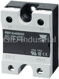
CARLO GAVAZZI RM1A48D50
Description
SSR, Hockey Puck, 50A, 3-32VDC Control Voltage, Zero Switching, 230VAC Operating Range
These are the most commonly used solid state relays in the industry today! The RM1A (zero switching) and RM1B (instant-on) series can be used in a wide range of applications including resistive, inductive and capacitive loads. The RM1A series is a single phase, zero switching (also called zero cross) solid state relay. Applications include plastics molding machinery, packaging machines, soldering equipment and food processing equipment.
Part Number
RM1A48D50
Price
Request Quote
Manufacturer
CARLO GAVAZZI
Lead Time
Request Quote
Category
Solid State Relays » Hockey Puck
Specifications
Part Number
RM1A48D50
Product Series
RM1A
Control Voltage
3 to 32VDC
Amp Rating
50 Amp
Type of Relay
Hockey Puck
Output Switching
Zero Crossing
Operating Voltage
480VAC
Phase
Single Phase
Ratings
No
Availability
Standard Stock
Weight - lbs.
0.1520
Base Unit of Measure
Each
Categorization Information
Solid State Relays
SSR, Hockey Puck, 50A, 3-32VDC Control Voltage,-RM1A48D50
Features
- AC solid state relay
- Zero Switching (RM1A) or Instant-On (RM1B)
- Available in: 230AC (23), 480VAC (48), 600VAC (60)
- Control voltage: 20-280VAC/22-48VDC (A) or 3-32VDC (D)
- 25, 50, 75 or 100 amps
- Builtin-in varistor
- Clip-on IP20 protection cover
- Can be used for resistive, inductive and capacitive loads
- LED indicator
Datasheet

Extracted Text
Solid State Relays Industrial, 1-Phase ZS (IO) w. LED and Built-in Varistor Types RM 23, RM 40, RM 48, RM 60 • Zero switching (RM1A) or instant-on switching (RM1B) AC Solid State Relay • Direct copper bonding (DCB) technology • LED indication • Built-in varistor • Clip-on IP 20 protection cover • Self-lifting terminals • Housing free of moulding mass • 2 input ranges: 3-32* VDC and 20-280VAC/22-48VDC • Operational ratings: Up to 100AACrms and 600VACrms • Blocking voltage: Up to 1400V p • Opto-isolation: > 4000VACrms • CE, RoHS compliant • cURus, CSA, CCC Product Description Ordering Key RM 1 A 23 D 25 The industrial, 1-phase relay with DC control input can be Solid State Relay with antiparallel thyristor out- used for phase control. The Number of poles put is the most widely used built-in varistor secures tran- Switching mode industrial SSR due to its mul- sient protection for the heavy Rated operational voltage tiple application possibilities. industrial applications, and Control voltage The relay can be used for the LED indicates the status Rated operational current resistive, inductive and of the control input. The clip- capacitive loads. The zero on cover is securing touch switching relay switches ON protection to IP 20. Protect- when the sinusoidal curve ed output terminals can han- 2 crosses zero and switches dle cables up to 16mm . OFF when the current cross- es zero. The instant-on relay Type Selection Switching mode Rated operational Control voltage Rated operational voltage current A: Zero Switching 23: 230VACrms A: 20-280VAC/22-48VDC 25: 25AACrms B: Instant-on switching 40: 400VACrms D: 3-32VDC* 50: 50AACrms (DC Control only) 48: 480VACrms *4 to 32VDC for 400, 480 and 600VAC types 75: 75AACrms 60: 600VACrms *4 to 32VDC for RM1B types 100: 100AACrms Selection Guide Rated opera- Blocking Control Rated operational current tional voltage voltage voltage 25A 50A 75A 100A 230VACrms 650V 3 - 32VDC RM1A23D25 RM1A23D50 RM1A23D75 RM1A23D100 p 20 to 280VAC RM1A23A25 RM1A23A50 RM1A23A75 RM1A23A100 22 to 48VDC 400VACrms 850Vp 4 - 32VDC RM1A40D25 RM1A40D50 RM1A40D75 RM1A40D100 20 to 280VAC RM1A40A25 RM1A40A50 RM1A40A75 RM1A40A100 22 to 48VDC 480VACrms 1200V 4 - 32VDC RM1A48D25 RM1A48D50 RM1A48D75 RM1A48D100 p 20 to 280 VAC RM1A48A25 RM1A48A50 RM1A48A75 RM1A48A100 22 to 48VDC 600VACrms 1400V 4 - 32VDC RM1A60D25 RM1A60D50 RM1A60D75 RM1A60D100 p 20 to 280VAC RM1A60A25 RM1A60A50 RM1A60A75 RM1A60A100 22 to 48VDC Specifications are subject to change without notice (25.06.2015) 1 RM1A, RM1B General Specifications RM1.23... RM1.40... RM1.48... RM1.60... Operational voltage range RM1A... 24 to 265VACrms 42 to 440VACrms 42 to 530VACrms 42 to 660VACrms RM1B... 42 to 265VACrms 42 to 440VACrms 42 to 530VACrms 42 to 660VACrms Blocking voltage ≥ 650V ≥ 850V ≥ 1200V ≥ 1400V p p p p Zero voltage turn-on ≤ 10V ≤ 10V ≤ 10V ≤ 10V Operational frequency range 45 to 65Hz 45 to 65Hz 45 to 65Hz 45 to 65Hz Power factor > 0.5 @ 230VACrms > 0.5 @ 400VACrms > 0.5 @ 480VACrms > 0.5 @ 600VACrms Approvals UR, cUR, CSA, CCC UR, cUR, CSA, CCC UR, cUR, CSA, CCC UR, cUR, CSA, CCC CE-marking Yes Yes Yes Yes * Isolation Input to Output 4000 Vrms 4000 Vrms 4000 Vrms 4000 Vrms input and Output to case 4000 Vrms 4000 Vrms 4000 Vrms 4000 Vrms * Heatsink must be connected to ground Input Specifications RM1...D.. RM1...A.. Control voltage range RM1A23... 3 - 32VDC 20 - 280VAC, 22 - 48VDC RM1A40... RM1A48... RM1A60... 4 - 32VDC 20 - 280VAC, 22 - 48VDC RM1B... 4 - 32VDC - Pick-up voltage @ Ta = 25˚C RM1A23... 2.5VDC 18VAC/DC RM1A40... RM1A48... RM1A60... 3.5VDC 18VAC/DC RM1B ... 3.5VDC - Reverse voltage 32VDC - Drop out voltage 1.2VDC 6VAC/DC Input current @ max input voltage RM1A ≤12 mA ≤ 20mA RM1B ≤15 mA - Response time pick-up RM1A 1/2 cycle 12ms RM1B 0.1ms - Response time drop-out 1/2 cycle 40ms Output Specifications RM1....25 RM....50 RM1....75 RM1....100 Rated operational current AC51 @ Ta=25°C 25Arms 50Arms 75Arms 100Arms AC53a @ Ta=25°C 5Arms 15Arms 20Arms 30Arms Min. operational current 150mA 250mA 400mA 500mA Rep. overload current t=1 s < 55AACrms < 125AACrms < 150AACrms < 200AACrms Non-rep. surge current t=10 ms 325A 600A 1150A 1900A p p p p Off-state leakage current @ rated voltage and frequency < 3mArms < 3mArms < 3mArms < 3mArms 2 2 2 2 2 I t for fusing t=10 ms < 525A s < 1800A s < 6600A s < 18000A s On-state voltage drop @ rated current 1.6Vrms 1.6Vrms 1.6Vrms 1.6Vrms Critical dV/dt off-state min. 1000V/μs 1000V/μs 1000V/μs 1000V/μs Endurance testing acc. to UL508 100,000 cycles 100,000 cycles 100,000 cycles 6,000 cycles Note: UL requirement for General Use Endurance testing is 6,000 cycles 2 Specifications are subject to change without notice (25.06.2015) RM1A,RM1B Motor Ratings*: HP (UL508) 230VAC 400VAC 480VAC 600VAC RM1..25 1.5HP 3HP 3HP 5HP RM1..50 3HP 5HP 7.5HP 10HP RM1..75 5HP 10HP 10HP 15HP RM1..100 7.5HP 15HP 20HP 25HP * with suitable heatsink Electromagnetic Compatibility Radiated Radio Frequency EMC Immunity IEC/EN 61000-6-2 Immunity IEC/EN 61000-4-3 Electrostatic Discharge (ESD) 10V/m, 80 - 1000 MHz Performance Criteria 1 Immunity IEC/EN 61000-4-2 10V/m, 1.4 - 2.0GHz Performance Criteria 1 Air discharge, 8kV Performance Criteria 2 3 V/m, 2.0 - 2.7GHz Performance Criteria 1 Contact, 4kV Performance Criteria 2 Conducted Radio Frequency IEC/EN 61000-4-6 Electrical Fast Transient Immunity (Burst) Immunity IEC/EN 61000-4-4 10V/m, 0.15 - 80 MHz Performance Criteria 1 Output: 2kV, 5kHz Performance Criteria 1 Voltage Dips Immunity IEC/EN 61000-4-11 0% for 10ms Performance Criteria 2 Input: 1kV, 5kHz Performance Criteria 1 70% for 500ms Performance Criteria 2 Electrical Surge Immunity IEC/EN 61000-4-5 Voltage Interruptions Immunity IEC/EN 61000-4-11 Output, line to line, 1kV Performance Criteria 2 0% for 5000ms Performance Criteria 2 Output, line to earth, 2kV Performance Criteria 2 Input, line to line, 1kV Performance Criteria 2 Input, line to earth, 2kV Performance Criteria 2 Radio Interference EMC Emission IEC/EN 61000-6-4 Field Emission (Radiated) IEC/EN 55011 Radio Interference Voltage Emission (Conducted) IEC/EN 55011 30 - 1000MHz Class B 0.15 - 30MHz Class A (industrial) with filters IEC/EN 60947-4-3 Class A (no filtering needed up to 75AAC) Notes: - Control input lines must be installed together to maintain products’ susceptibility to Radio Frequency interference. - Performance Criteria 1: No degradation of performance or loss of function is allowed when the product is operated as intended. - Performance Criteria 2: During the test, degradation of performance or partial loss of function is allowed. However, when the test is complete the product should return operating as intended by itself. - Performance Criteria 3: Temporary loss of function is allowed, provided the function can be restored by manual operation of the controls. Specifications are subject to change without notice (25.06.2015) 3 RM1A, RM1B Thermal Specifications RM1....25 RM1....50 RM1.60.50 RM1....75 RM1....100 Operating temperature range -20° to 70°C -20° to 70°C -20° to 70°C -20° to 70°C -20° to 70°C Storage temperature range -40° to 100°C -40° to 100°C -40° to 100°C -40° to 100°C -40° to 100°C Junction temperature ≤ 125°C ≤ 125°C ≤ 125°C ≤ 125°C ≤ 125°C Rth junction to case ≤ 0.80°C/W ≤ 0.50°C/W ≤ 0.72°C/W ≤ 0.35°C/W ≤ 0.30°C/W R junction to ambient ≤ 20.0°C/W ≤ 20.0°C/W ≤ 20.0°C/W ≤ 20.0°C/W ≤ 20.0°C/W th Housing Specifications Weight Relay 25A, 50A Approx. 60g Mounting screws M5 75A, 100A Approx. 100g Mounting torque 1.5-2.0Nm Baseplate Control terminal 25A, 50A Aluminium Mounting screws M3 x 9 75A, 100A Copper, nickel-plated Mounting torque 0.5Nm Potting compound None Power terminal Mounting screws M5 x 9 Mounting torque 2.4Nm Connection Specifications Connection terminals L1, T1 A1, A2 Stripping length (X) 12 mm 8 mm Connection Type M5 screw with captivated washer M3 screw with captivated washer Rigid (solid & stranded) X UR rated data 1x 2.5 - 6.0 mm² 2x 2.5 - 6.0 mm² 1x 0.5 - 2.5 mm² 2x 0.5 - 2.5 mm² 1x 14 - 10 AWG 2x 14 - 10 AWG 1x 18 - 12 AWG 2x 18 - 12 AWG Flexible with end sleeve 2x 1.0 - 2.5 mm² 1x 1.0 - 4.0 mm² 2x 2.5 - 4.0 mm² 1x 0.5 - 2.5 mm² 2x 0.5 - 2.5 mm² 1x 18 - 12 AWG 1x 18 - 14 AWG 1x 18 - 12 AWG 1x 18 - 12 AWG 1x 14 - 12 AWG Flexible without end sleeve 2x 1.0 - 2.5 mm² 1x 1.0 - 6.0 mm² 2x 2.5 - 6.0 mm² 1x 18 - 10 AWG 1x 18 - 14 AWG 1x 14 - 10 AWG Torque specification Pozidrive 2 Pozidrive 1 2.4 Nm (21.2 lb-in) 0.5 Nm (4.4 lb-in) Aperture for termination lug 12 mm 7.5 mm 4 Specifications are subject to change without notice (25.06.2015) RM1A, RM1B Functional Diagram Dimensions + A1() REGULATION T1 ~ * ZC ZC IO - A2() ~ L1 LED APPLY HEATSINK COMPOUND All dimensions in mm * Varistor across input applies to AC control versions only. Connection Diagram L1 L2/N * LOAD ~ ~ ( ) ( ) + - Control Input * Depends on system requirements Specifications are subject to change without notice (25.06.2015) 5 RM1A, RM1B Heatsink Dimensions (load current versus ambient temperature) RM....25 RM....50 Load Thermal resistance Load Thermal resistance Power Power current [A] [°C/W] current [A] [°C/W] dissipation [W] dissipation [W] 25.0 28 50.0 61 2.70 2.34 1.98 1.61 1.25 0.89 1.03 0.86 0.70 0.53 0.37 0.20 22.5 24 45.0 53 3.10 2.69 2.28 1.86 1.45 1.04 1.27 1.09 0.90 0.71 0.52 0.33 20.0 21 40.0 46 3.61 3.13 2.65 2.18 1.70 1.23 1.54 1.32 1.10 0.89 0.67 0.45 17.5 4.26 3.70 3.14 2.59 2.03 1.47 18 35.0 1.85 1.59 1.34 1.08 0.82 0.57 39 15.0 5.14 4.47 3.80 3.14 2.47 1.80 15 30.0 2.26 1.95 1.65 1.34 1.03 0.72 33 12.5 6.38 5.56 4.73 3.91 3.09 2.27 12 25.0 2.85 2.47 2.08 1.70 1.32 0.94 26 10.0 8.25 7.19 6.14 5.08 4.02 2.97 9 20.0 3.73 3.24 2.75 2.26 1.77 1.27 20 11.4 9.94 8.49 7.04 5.59 4.14 5.22 4.54 3.86 3.19 2.51 1.83 7.5 7 15.0 15 17.7 15.4 13.2 11.0 8.74 6.51 8.21 7.16 6.11 5.05 4.00 2.95 5.0 4 10.0 10 -- - - 18.2 13.6 17.2 15.0 12.9 10.7 8.51 6.33 2.5 2 5.0 5 20 30 40 50 60 70 20 30 40 50 60 70 T T A A Ambient temp. [°C] Ambient temp. [°C] Junction to ambient thermal resistance, R < 20.0 °C/W Junction to ambient thermal resistance, R < 20.0 °C/W th j-a th j-a Junction to case thermal resistance, R < 0.80 °C/W Junction to case thermal resistance, R < 0.50 °C/W th j-c th j-c 2 2 Case to heatsink thermal resistance, R < 0.20 °C/W Case to heatsink thermal resistance, R < 0.20 °C/W th c-s th c-s Maximum allowable case temperature 100 °C Maximum allowable case temperature 100 °C Maximum allowable junction temperature 125 °C Maximum allowable junction temperature 125 °C RM1.60..50 RM....75 Load Thermal resistance Power Load Thermal resistance Power current [A] [°C/W] dissipation [W] current [A] [°C/W] dissipation [W] 0.91 0.78 0.65 0.52 0.39 0.26 77 75.0 50.0 55 0.99 0.81 0.63 0.44 0.26 0.08 1.10 0.96 0.81 0.66 0.51 0.36 68 67.5 45.0 48 1.28 1.07 0.86 0.65 0.44 0.23 1.34 1.17 1.00 0.83 0.66 0.49 59 60.0 40.0 1.64 1.40 1.15 0.91 0.67 0.42 41 1.60 1.40 1.20 1.00 0.80 0.60 50 52.5 35.0 2.11 1.82 1.54 1.25 0.96 0.67 35 1.93 1.68 1.44 1.20 0.96 0.72 42 45.0 30.0 2.60 2.25 1.90 1.55 1.20 0.85 29 2.38 2.08 1.78 1.49 1.19 0.89 34 37.5 25.0 3.30 2.86 2.43 1.99 1.55 1.11 23 3.06 2.68 2.30 1.91 1.53 1.15 26 4.36 3.79 3.22 2.65 2.08 1.51 30.0 20.0 18 4.21 3.68 3.16 2.63 2.10 1.58 19 6.1 5.4 4.6 3.77 2.97 2.18 22.5 15.0 13 6.51 5.70 4.88 4.07 3.26 2.44 12 9.76 8.52 7.3 6.0 4.8 3.54 15.0 10.0 8 -- -- 15.47 12.85 10.24 7.6 13.5 11.77 10.09 8.41 6.73 5.04 6 7.5 5.0 4 20 30 40 50 60 70 20 30 40 50 60 70 TA T A Ambient temp. [°C] Ambient temp. [°C] Junction to ambient thermal resistance, R < 20.0 °C/W Junction to ambient thermal resistance, R < 20.0 °C/W th j-a th j-a Junction to baseplate case thermal resistance, R < 0.72 °C/W Junction to case thermal resistance, R < 0.35 °C/W th j-c th j-c 2 2 Case to heatsink thermal resistance, Rth c-s < 0.20 °C/W Case to heatsink thermal resistance, R < 0.10 °C/W th c-s Maximum allowable heatsink temperature 100 °C Maximum allowable heatsink temperature 100 °C Maximum allowable junction temperature 125 °C Maximum allowable junction temperature 125 °C 6 Specifications are subject to change without notice (25.06.2015) RM1A, RM1B Heatsink Dimensions (load current versus ambient temperature) cont. RM....100 Load Thermal resistance Power current [A] [°C/W] dissipation [W] 0.54 0.45 0.36 0.27 0.18 0.09 111 100.0 0.68 0.58 0.47 0.37 0.27 0.17 97 90.0 0.86 0.74 0.62 0.50 0.38 0.26 84 80.0 1.08 0.94 0.80 0.66 0.52 0.38 71 70.0 1.37 1.20 1.03 0.85 0.68 0.51 59 60.0 1.70 1.49 1.28 1.06 0.85 0.64 47 50.0 2.21 1.93 1.66 1.38 1.10 0.83 36 40.0 3.06 2.68 2.30 1.91 1.53 1.15 26 Junction to ambient thermal resistance, R < 20.0 °C/W th j-a 30.0 Junction to case thermal resistance, R < 0.30 °C/W th j-c 4.78 4.18 3.59 2.99 2.39 1.79 17 20.0 2 Case to heatsink thermal resistance, R < 0.10 °C/W th c-s 9.98 8.73 7.49 6.24 4.99 3.74 8 10.0 Maximum allowable heatsink temperature 100 °C 20 30 40 50 60 70 T A Maximum allowable junction temperature 125 °C Ambient temp. [°C] 2. Thermal resistance case to heatsink valves are applicable upon application of a fine layer of silicon based thermal paste HTS02S from Electrolube between SSR and heatsink. Heatsink Selection Ordering Key RHS.. • Heatsinks and fans o o • 5.40 C/W to 0.12 C/W thermal resistance • DIN, panel or thru wall mounting • Single or multiple SSR mounting Heatsink Range Overview: http://www.productselection.net/PDF/UK/ssr_accessories.pdf Heatsink Selector Tool: http://www.productselection.net/heatsink/heatsinkselector.php?LANG=UK Specifications are subject to change without notice (25.06.2015) 7 RM1A, RM1B Short Circuit Protection Protection Co-ordination, Type 1 vs. Type 2: Type 1 protection implies that after a short circuit, the device under test will no longer be in a functioning state. In type 2 co-ordination the device under test will still be functional after the short circuit. In both cases, however, the short circuit has to be interrupted. The fuse between enclosure and supply shall not open. The door or cover of the enclosure shall not be blown open. There shall be no damage to conductors of terminals and the conductors shall not separate from terminals. Therese shall be no breakage or cracking of insulating bases to the extent that the integrity of the mounting of live parts is impaired. Discharge of parts or any risk of fire shall not occur. The product variants listed in the table hereunder are suitable for use on a circuit capable of delivering not more than 65,000A rms Symmetrical Amperes, 600Volts maximum when protected by fuses. Tests at 65,000A were performed with Class J, fast acting: please refer to the table below for maximum allowed ampere rating of the fuse. Use fuses only. Co-ordination type 1 (UL508) Part No. Prospective short Max. fuse size [A] Class/ Model Voltage [VAC] circuit current [kArms] RM1..25.. 65 30 J or CC 600 RM1..50.. 65 30 J 600 20 HSJ20 (Mersen*) 600 RM1..75.. 65 80 J 600 60 HSJ60 (Mersen*) 600 RM1..100.. 65 80 J 600 60 HSJ60 (Mersen*) 600 Co-ordination type 2 (IEC/EN60947-4-3) Part No. Prospective short Max. fuse Brand Model Size circuit current [kArms] size [A] RM1.xx.25.. (xx = 23, 40 or 48) 10 25 Mersen* 6.9 gRB 10-25 10.3 x 38 RM1.60.25.. 10 20 Mersen* 6.9 gRB 10-20 10.3 x 38 RM1.xx.50.. (xx = 23 or 40) 10 50 Mersen* 6.9zz CP gRC 14x51/50 14 x 51 RM1.xx.50.. (xx = 48 or 60) 10 50 Mersen* 6.9zz CP gRC 22x58/50 22 x 58 RM1.xx.75.. (xx = 23, 40, 48 or 60) 10 63 Mersen* 6.9zz CP gRC 22x58/63 22 x 58 RM1.xx.100.. (xx = 23, 40, 48 or 60) 10 100 Mersen* 6.9zz CP gRC 22x58/100 22 x 58 zz = 00, without fuse trip indication zz = 21, with fuse trip indication * Formerly Ferraz Shawmut 8 Specifications are subject to change without notice (25.06.2015) RM1A, RM1B Type 2 Protection with Miniature Circuit Breakers (M.C.B.s) Solid State Relay ABB Model no. for ABB Model no. for Wire cross Minimum length of * 2 type Z - type M. C. B. B - type M. C. B. sectional area [mm ] Cu wire conductor [m] (rated current) (rated current) RM1..25.. 1-pole S201-Z4 (4A) S201-B2 (2A) 1.0 21.0 S201-Z6 UC (6A) S201-B2 (2A) 1.0 21.0 1.5 31.5 RM1..50.. 1-pole S201-Z10 (10A) S201-B4 (4A) 1.0 7.6 1.5 11.4 2.5 19.0 S201-Z16 (16A) S201-B6 (6A) 1.0 5.2 1.5 7.8 2.5 13.0 4.0 20.8 S201-Z20 (20A) S201-B10 (10A) 1.5 12.6 2.5 21.0 S201-Z25 (25A) S201-B13 (13A) 2.5 25.0 4.0 40.0 2-pole S202-Z25 (25A) S202-B13 (13A) 2.5 19.0 4.0 30.4 RM1..75.. 1-pole S201-Z20 (20A) S201-B10 (10A) 1.5 4.2 2.5 7.0 4.0 11.2 S201-Z32 (32A) S201-B16 (16A) 2.5 13.0 4.0 20.8 6.0 31.2 2-pole S202-Z20 (20A) S202-B10 (10A) 1.5 1.8 2.5 3.0 4.0 4.8 S202-Z32 (32A) S202-B16 (16A) 2.5 5.0 4.0 8.0 6.0 12.0 10.0 20.0 S202-Z50 (50A) S202-B25 (25A) 4.0 14.8 6.0 22.2 10.0 37.0 RM1..100.. 1-pole S201-Z50 (50A) S201-B25 (25A) 4.0 4.8 6.0 7.2 10.0 12.0 16.0 19.2 S201-Z63 (63A) S201-B32 (32A) 6.0 7.2 10.0 12.0 16.0 19.2 * Between MCB and Load (including return path which goes back to the mains). Note: A prospective current of 6kA and a 230/400V power supply system is assumed for the above suggested specifications. For cables with different cross section than those mentioned above please consult Carlo Gavazzi's Technical Support Group. Specifications are subject to change without notice (25.06.2015) 9 RM1A, RM1B FASTON terminals • Faston tabs Ordering Key • Tab dimensions accord- ing to DIN 46342 part 1 Screw mounted * RM1A48D25 F 4 • Pure tin-plated brass Faston terminals RS, RM Solid State Relay Faston terminals Tab orientation Input Tab width: 4.8mm Output Tab width: 6.3mm Faston terminals * ** RM48 F4 in packs of 20 RS, RM Solid State Relay Tab orientation * 0: Flat (0º) 4: Angled (45º) ** 48: 4.8mm faston for input 63: 6.3mm faston for output Fork Terminals • Terminal adaptors 2 Ordering Key for 35mm cable RM635FK P • Type RM635FK RM terminal adaptor • Pack size: 20 pieces Touch protected (optional) Other Accessories • Graphite thermal pad • Touch safety cover with adhesive on one • Type RMIP20 side • IP20 protection degree • Type KK071CUT • Pack size: 20 pieces • Dimensions: 35 x 43 x 0.25mm • Packing quantity: 50pcs. All accessories can be ordered pre-assembled with Solid State Relays. Other accessories include DIN rail adaptors, fuses, varistors and spacers. For futher information refer to Accessories datasheets at: www.productselection.net/PDF/UK/SSR_Accessories.pdf 10 Specifications are subject to change without notice (25.06.2015)
Frequently asked questions
Why choose IPC Station?

What is IPC Station' warranty policy for the RM1A48D50?
What carriers does IPC Station use to ship parts?
Does IPC Station sell to international (non-USA) customers?
What methods of payment does IPC Station accept?
Why buy from GID?

Quality
We are industry veterans who take pride in our work

Protection
Avoid the dangers of risky trading in the gray market

Access
Our network of suppliers is ready and at your disposal

Savings
Maintain legacy systems to prevent costly downtime

Speed
Time is of the essence, and we are respectful of yours
Related Products
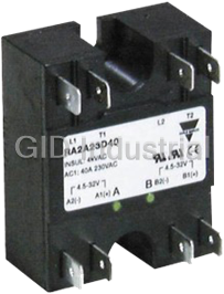
SSR, Hockey Puck, 40A, 4.5-32VDC Control Voltage, Zero Switching, Dual Output, Two Pole, 230VAC This...
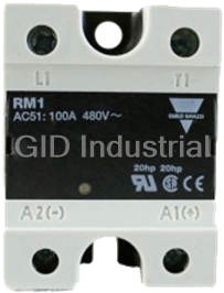
SSR, Hockey Puck, 75A, 20-280VAC Control Voltage, Zero Switching, 230VAC Operating Range These are t...
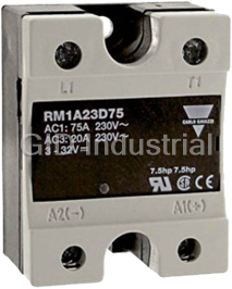
SSR, Hockey Puck, 75A, 3-32VDC Control Voltage, Zero Switching, 230VAC Operating Range These are the...
SSR, Hockey Puck, 25A, 24-265VAC Control Voltage, Zero Switching, 480VAC Operating Range These are t...
SSR, Hockey Puck, 50A, 24-265VAC Control Voltage, Zero Switching, 480VAC Operating Range These are t...
SSR, Hockey Puck, 75A, 24-265VAC Control Voltage, Zero Switching, 480VAC Operating Range These are t...
Request a Quote

The quote request has been received
Close

Facing challenges or have inquiries? Feel free to contact us!
Call Us +1-469-283-2440
What they say about us
FANTASTIC RESOURCE
One of our top priorities is maintaining our business with precision, and we are constantly looking for affiliates that can help us achieve our goal. With the aid of GID Industrial, our obsolete product management has never been more efficient. They have been a great resource to our company, and have quickly become a go-to supplier on our list!
Bucher Emhart Glass
EXCELLENT SERVICE
With our strict fundamentals and high expectations, we were surprised when we came across GID Industrial and their competitive pricing. When we approached them with our issue, they were incredibly confident in being able to provide us with a seamless solution at the best price for us. GID Industrial quickly understood our needs and provided us with excellent service, as well as fully tested product to ensure what we received would be the right fit for our company.
Fuji
HARD TO FIND A BETTER PROVIDER
Our company provides services to aid in the manufacture of technological products, such as semiconductors and flat panel displays, and often searching for distributors of obsolete product we require can waste time and money. Finding GID Industrial proved to be a great asset to our company, with cost effective solutions and superior knowledge on all of their materials, it’d be hard to find a better provider of obsolete or hard to find products.
Applied Materials
CONSISTENTLY DELIVERS QUALITY SOLUTIONS
Over the years, the equipment used in our company becomes discontinued, but they’re still of great use to us and our customers. Once these products are no longer available through the manufacturer, finding a reliable, quick supplier is a necessity, and luckily for us, GID Industrial has provided the most trustworthy, quality solutions to our obsolete component needs.
Nidec Vamco
TERRIFIC RESOURCE
This company has been a terrific help to us (I work for Trican Well Service) in sourcing the Micron Ram Memory we needed for our Siemens computers. Great service! And great pricing! I know when the product is shipping and when it will arrive, all the way through the ordering process.
Trican Well Service
GO TO SOURCE
When I can't find an obsolete part, I first call GID and they'll come up with my parts every time. Great customer service and follow up as well. Scott emails me from time to time to touch base and see if we're having trouble finding something.....which is often with our 25 yr old equipment.
ConAgra Foods