

 Manufacturers
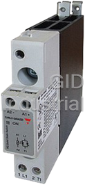
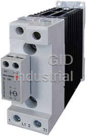
CARLO GAVAZZI RGC1A23D30KGU
Description
SSR w/Heatsink, 30AAC, 3/4-32VDC Control Voltage, Zero Crossing, Screw, Box Clamp, 230V
Carlo Gavazzi's RGC1A series are solid state relays with an integrated single phase heatsink. The RGC1A relays are zero cross (RGC1B is instant on switching). Available in: 230V (RGC1A23) or 600V (RGC1AA60) Control voltage: 3 or 4-32VDC (D) or 20-275VAC/24-190VDC (A) Rated current: 15 to 90 Screw (K) or box clamp (G) A 'P' at the end of the part number means over-temperature protection option
Part Number
RGC1A23D30KGU
Price
Request Quote
Manufacturer
CARLO GAVAZZI
Lead Time
Request Quote
Category
Solid State Relays
Specifications
Part Number
RGC1A23D30KGU
Product Series
RGC
Control Voltage
3 or 4-32VDC
Amp Rating
30 Amp
Type of Relay
SSR w/Heatsink
Output Switching
Zero Crossing
Operating Voltage
230VAC
Phase
Single Phase
Ratings
UL508
Weight - lbs.
0.8270
Base Unit of Measure
Each
Categorization Information
Solid State Relays
SSR w/Heatsink, 30AAC, 3/4-32VDC Control Voltage,-RGC1A23D30KGU
Datasheet

Extracted Text
Solid State Relays 1-Phase Integrated Heatsink Zero Cross or Instant On Switching Types RGC Solid State Contactor 'U' Connection • Product Width ranging from 17.5mm up to 70mm • Rated Operational voltage: Up to 600VAC • Rated Operational current: Up to 85AAC @ 40°C • Up to 18000A²s for I²t and 1200Vp blocking voltage • Control voltages: 3-32 VDC, 20-275 VAC (24-190 VDC) • IP20 protection • Design according to EN/IEC60947-4-2, EN/IEC60947-4-3, EN/IEC62314, UL508, CSA 22-2 No. 14-10 • Integrated voltage transient protection with varistor • RoHS compliant • Short circuit current rating: 100kA • VDE approval 1 • Germanischer Lloyd approval Product Description Ordering Key RGC 1 A 60 A 40 K G U _ Solid State Relay This new range of solid state The nominal current ratings Number of poles contactors presents a unique are at 40˚C. The smallest opportunity to maximize effi- width is 17.5mm and is rated Switching Mode ciency in panel space and is an at 20 AAC. Power and control Rated Operational Voltage evolution of solid state switch- teminals allow for safe looping Control voltage es for which Carlo Gavazzi is of cables. Rated Operational current very well known. Connection type for control Connection type for power Voltage transient protection is standard across the output with a varistor. Connection configuration Specifications are stated at 25°C unless otherwise noted. Option 1. Germanischer Lloyd approval applicable only to models RGC...15KGU, RGC...20KGU, RGC...25KGU and RGC...30KGU Ordering Key (Refer to page 2 for available part numbers) 1Phase SSR Rated Voltage, Control Voltage Rated Connection Connection Connection 2 with heatsink Blocking Voltage Current at 40˚C Control Power Configuration Option 4 RGC1A: ZC 23: 230V +10% - 15%, 800Vp D: 3 or 4-32VDC 15: 20AAC, 525A²s K: Screw G: Box Clamp U: SSR P: Overtemperature 4 RGC1B: IO 60: 600V +10% -15%, 1200Vp A: 20 - 275VAC, 20: 23AAC, 525A²s G: Box clamp protection 3 24-190 VDC 25: 25AAC, 1800A²s (OTP) 30: 30AAC, 1800A²s 40: 40AAC, 3200A²s 42: 43AAC, 18000A²s 60: 60AAC, 3200A²s 62: 65AAC, 18000A²s 90: 85AAC, 6600A²s 2. Refer to derating curves 3. Default control connection for RGC...P is Box Clamp. See connections specifications. 4: ZC = Zero Cross switching, IO = Instant On switching Specifications are subject to change without notice (13.11.2015) 1 RGC...U Selection Guide o 2 Rated voltage, Control voltage Connection Rated operational current @ 40 C (I t value) Blocking voltage, Control/ Power Product width Switching mode 20 AAC (525A²s) 23 AAC (525A²s) 25 AAC (1800A²s) 30 AAC (1800A²s) 17.5mm, low depth 17.5mm 17.5mm, low depth 22.5mm 230V, 800Vp 3-32VDC Screw/Box RGC1A23D15KGU RGC1A23D20KGU RGC1A23D25KGU RGC1A23D30KGU ZC 20-275VAC, 24-190VDC Screw/Box RGC1A23A15KGU RGC1A23A20KGU RGC1A23A25KGU RGC1A23A30KGU 40 AAC (3200A²s) 43 AAC (18000A²s) 60 AAC (3200A²s) 65 AAC (18000A²s) 35mm 35mm 70mm 70mm 3-32VDC Screw/Box RGC1A23D40KGU RGC1A23D42KGU RGC1A23D60KGU RGC1A23D62KGU 20-275VAC, 24-190VDC Screw/Box RGC1A23A40KGU RGC1A23A42KGU RGC1A23A60KGU RGC1A23A62KGU 20 AAC (525A²s) 23 AAC (525A²s) 25 AAC (1800A²s) 30 AAC (1800A²s) 17.5mm, low depth 17.5mm 17.5mm, low depth 22.5mm 600V,1200Vp 4-32VDC Screw/Box RGC1A60D15KGU RGC1A60D20KGU RGC1A60D25KGU RGC1A60D30KGU ZC 20-275VAC, 24-190VDC Screw/Box RGC1A60A15KGU RGC1A60A20KGU RGC1A60A25KGU RGC1A60A30KGU 40 AAC (3200A²s) 43 AAC (18000A²s) 60 AAC (3200A²s) 65 AAC (18000A²s) 35mm 35mm 70mm 70mm 4-32VDC Screw/Box RGC1A60D40KGU RGC1A60D42KGU RGC1A60D60KGU RGC1A60D62KGU 20-275VAC, 24-190VDC Screw/Box RGC1A60A40KGU RGC1A60A42KGU RGC1A60A60KGU RGC1A60A62KGU 20 AAC (525A²s) 23 AAC (525A²s) 25 AAC (1800A²s) 30 AAC (1800A²s) 17.5mm, low depth 17.5mm 17.5mm, low depth 22.5mm 600V, 1200Vp 4-32VDC Screw/Box RGC1B60D15KGU RGC1B60D20KGU RGC1B60D25KGU RGC1B60D30KGU IO 40 AAC (3200A²s) 43 AAC (18000A²s) 60 AAC (3200A²s) 65 AAC (18000A²s) 35mm 35mm 70mm 70mm 4-32VDC Screw/Box RGC1B60D40KGU RGC1B60D42KGU RGC1B60D60KGU RGC1B60D62KGU Selection Guide - RGC..P (Integrated Overtemperature Protection) o 2 Rated voltage, Control voltage Connection Rated operational current @ 40 C (I t value) Blocking voltage, Control/ Power Product width Switching mode 85AAC (6600A²s) 70mm + fan 230V, 800Vp 5-32VDC Box/Box RGC1A23D90GGUP ZC 40 AAC (3200A²s) 60 AAC (3200A²s) 85 AAC (3200A²s) 35mm 70mm 70mm + fan 600V, 1200Vp 5-32VDC Box/Box RGC1A60D40GGUP RGC1A60D60GGUP RGC1A60D90GGUP ZC 20-275VAC, 24-190VDC Box/Box RGC1A60A40GGUP RGC1A60A60GGUP RGC1A60A90GGUP 85AAC (6600A²s) 70mm + fan 600V, 1200Vp 5-32VDC Box/Box RGC1B60D90GGUP IO 2 Specifications are subject to change without notice (13.11.2015) RGC...U Output Voltage Specifications RGC..23.. RGC..60.. Operational Voltage Range 24-240 VAC, 42-600 VAC, +10%, -15% on max +10% -15% on max Blocking Voltage 800Vp 1200 Vp Internal Varistor 275V 625V General Specifications Latching voltage Over-voltage category III (across L1-T1)20V (fixed installations) Operational frequency Isolation range 45 to 65Hz Input to Output RGC... 4000 Vrms RGC...D..P 2500 Vrms Power factor > 0.5 @ Vrated RGC...A..P 4000 Vrms Touch Protection IP20 Input and Output RGC... 4000 Vrms Control input status continuously ON Green LED, to case RGC...D..P 4000 Vrms when control input is applied RGC...A..P 4000 Vrms Pollution degree 2 Input to Fan/ Alarm Output (non-conductive pollution with RGC...A..P 2500 Vrms possibilities of condensation) Specifications are subject to change without notice (13.11.2015) 3 RGC...U Output Specifications RGC..15.. RGC..20.. RGC..25.. RGC..30.. 6 Rated operational current AC-51 rating @ Ta=25°C 20 AAC 25.5 AAC 30 AAC 30 AAC AC-51 rating @ Ta=40°C 20 AAC 23 AAC 25 AAC 30 AAC AC-53a rating @ Ta=40°C 5 AAC 5 AAC 5 AAC 8 AAC Number of motor starts 5 (x:6, Tx:6s, F:50%) at 40˚C 30 30 30 30 Min. operational current 150 mAAC 150 mAAC 250 mAAC 250 mAAC Rep. overload current - (Motor Rating) PF = 0.4 - 0.5 UL508: TAMB=40°C, tON=1s, tOFF=9s, 50cycles 51 AAC 60 AAC 51 AAC 84 AAC Maximum transient surge current (I ), t=10ms 325 Ap 325 Ap 600 Ap 600Ap TSM Maximum off-state leakage current at rated voltage 3 mAAC 3 mAAC 3 mAAC 3 mAAC I²t for fusing (t=10ms) Minimum 525 A²s 525 A²s 1800 A²s 1800 A²s Crititcal dv/dt (@ Tj init = 40°C) 1000 V/us 1000 V/us 1000 V/us 1000 V/us RGC..40.. RGC..42.. RGC..60.. RGC..62.. RGC..90.. 6 Rated operational current AC-51 rating @ Ta=25°C 47 AAC 50 AAC 70 AAC 75 AAC 85 AAC AC-51 rating @ Ta=40°C 40 AAC 43 AAC 60 AAC 65 AAC 85 AAC AC-53a rating @ Ta=40°C 13 AAC 16 AAC 14.8 AAC 20 AAC 18 AAC Number of motor starts 5 (x:6, Tx:6s, F:50%) at 40˚C 30 30 30 30 30 Min. operational current 400 mAAC 500 mAAC 400 mAAC 500 mAAC 400 mAAC Rep. overload current - (Motor Rating) PF = 0.4 - 0.5 UL508: T =40°C, t =1s, t =9s, AMB ON OFF 50cycles 126 AAC 126 AAC 126 AAC 168 AAC 168 ACC Maximum transient surge current (I ), t=10ms 800 Ap 1900 Ap 800 Ap 1900 Ap 1150 Ap TSM Maximum off-state leakage current at rated voltage 3 mAAC 3 mAAC 3 mAAC 3 mAAC 3 mAAC I²t for fusing (t=10ms) Minimum 3200 A²s 18000 A²s 3200 A²s 18000 A²s 6600 A²s Crititcal dv/dt (@ Tj init = 40°C) 1000 V/us 1000 V/us 1000 V/us 1000 V/us 1000 V/us 5. Overload current profile definition, x: multiple of AC53a rating, Tx: duration of current surge, F: duty cycle 6: refer to Derating Curves Overtemperature Alarm Specifications for RGC...P RGC..D..P RGC..A..P Output type PNP open collector _ Potential Free Normal state Closed Closed Maximum current rating 50 mADC 50 mADC 7,8 Rated voltage (EN61131-2: 2003) , Ua 24VDC -15%, +20% 24VDC -15%, +20% Rated voltage, Us RGC...D90GGUP 24VDC ± 10% N/A Fan rating, Uf RGC...A90GGUP N/A 24VDC ±10%, 50mA nominal Alarm voltage drop Typical 2.8VDC 1.8VDC Maximum 4VDC 3.5VDC Visual Indication Continous Red LED Continous Red LED Reverse polarity protection 24VDC 24VDC 7: DC supply for alarm signal should be supplied from a Class 2 power source 8: Maximum voltage to be applied between 11+ and 12- (Ua) terminals should be 35VDC maximum with reference to A2- 4 Specifications are subject to change without notice (13.11.2015) RGC...U Input specifications RGC..D.. RGC..A.. 9,10 Control voltage range RGC..23.. 3 - 32 VDC 20 - 275 VAC, 24 (-10%) - 190 VDC RGC..60.. 4 - 32 VDC 20-275 VAC, 24 (-10%) - 190 VDC RGC...P (Uc) 5 - 32 VDC 20-275 VAC, 24 (-10%) - 190 VDC Pick-up voltage RGC..23.. 3.0 VDC 20 VAC/DC RGC..60.. 3.8 VDC RGC...P 5 VDC 20 VAC/ 24VDC Drop-out voltage 1 VDC 5 VAC/DC Maximum Reverse voltage 32 VDC - Response time pick-up ZC (RGC1A..) 0.5 cycle + 500µs @ 24VDC 2 cycles @ 230VAC/110VDC Response time pick-up IO (RGC1B..) 350µs @ 24 VDC N/A Response time drop-out 0.5 cycle + 500µs @ 24VDC 0.5 cycle + 40ms @ 230VAC/ 110VDC Input current @ 40°C See diagrams below See diagrams below 9. DC control to be supplied by class 2 power source according to UL1310 10. For GL approved models control range for RGC1.23... is 4-32VDC and for RGC1.60... 5-32VDC R RG GC C1 1 .... A A : : iin np pu ut t c cu ur rr re en nt t v vs s iin np pu ut t v vo ollt ta ag ge e RG..A.. 4400m mA A 3355m mA A 3300m mA A 2255m mA A R RG GC C .... A A 2200m mA A 1155m mA A RGC..A..P (Normal Operation) 10mA RGC..A..P (Active Protection) 5mA 0mA 0VAC 50VAC 100VAC 150VAC 200VAC 250VAC 300VAC R RG GC C1 1 .... A A : : iin np pu ut t c cu ur rr re en nt t v vs s iin np pu ut t v vo ollt ta ag ge e 4400m mA A RGC..A..P (Active Protection) 3355m mA A 3300m mA A 2255m mA A 2200m mA A RGC .. A 1155m mA A 10mA RGC..A..P (Normal Operation) 5mA 0mA 0VDC 50VDC 100VDC 150VDC 200VDC 250VDC Specifications are subject to change without notice (13.11.2015) 5 RGC...U Input specifications (cont.) RG..D.. x A A1 1 C Ch ha ar ra ac ct te er riis st tiic cs s: : D DC C iin np pu ut t c cu ur rr re en nt t v vs s IIn np pu ut t v vo ollt ta ag ge e 2255..00m mA A RGC..D..P (Normal Operation) 2200..00m mA A RGC..D..P (Active Protection) 1155..00m mA A 1100..00m mA A 5.0mA 2V 4V 6V 8V 10V 12V 14V 16V 18V 20V 22V 24V 26V 28V 30V 32V 34V x: Input currents for RGC1..D15, RGC1..D20, RGC1..D25, RGC1..D30, RGC1..D4x, RGC1..D6x x y IIN N1 1 C Ch ha ar ra ac ct te er riis st tiic cs s: : D DC C iin np pu ut t c cu ur rr re en nt t v vs s IIn np pu ut t v vo ollt ta ag ge e 2200..00m mA A RGC..D90GGUP (Normal Operation) 1155..00m mA A 1100..00m mA A 55..00m mA A RGC..D90GGUP (Active Protection) 0.0mA 2V 4V 6V 8V 10V 12V 14V 16V 18V 20V 22V 24V 26V 28V 30V 32V 34V y: input currents valid only for RGC1..D90GGUP 6 Specifications are subject to change without notice (13.11.2015) RGC...U Motor Ratings: HP (UL508) / kW (EN/IEC60947-4-2) @ 40°C 115 VAC 230 VAC 400 VAC 480 VAC 600 VAC RGC..15 ⅓HP / 0.18kW 1HP / 0.37kW 2HP / 0.75kW 3HP / 1.1kW 3HP / 1.5kW RGC..20 ½HP / 0.18kW 1½HP / 0.37kW 2HP / 0.75kW 3HP / 1.1kW 3HP / 1.5kW RGC..25 ⅓HP / 0.18kW 1HP / 0.37kW 2HP / 0.75kW 3HP / 1.1kW 3HP / 1.5kW RGC..30 ¾HP / 0.37kW 2HP / 1.1kW 3HP / 1.5kW 5HP / 2.2kW 5HP / 3.7kW RGC..40 1HP / 0.56kW 3HP / 1.5kW 5HP / 2.2kW 5HP / 3.7kW 7½HP / 4kW RGC..42 1½HP / 0.56kW 3HP / 1.5kW 5HP / 2.2kW 7½HP / 3.7kW 10HP / 4kW RGC..60 1½HP / 0.56kW 3HP / 1.5kW 5HP / 3kW 7½HP / 4kW 10HP / 4kW RGC..62 2HP / 0.75kW 5HP / 1.5kW 7½HP / 4kW 10HP / 4kW 15HP / 5.5kW RGC..90 2HP / 0.75kW 5HP / 1.5kW 7½HP / 4kW 10HP / 4kW 15HP / 5.5kW Detailed Over temperature Alarm Procedure (for RGC...P) ALARM Signal and Fan ALARM Signal only (applicablA e LA to R R G M C .S .D ig 90 nG aG l U an Pd ) FAN ALARM Signal only ST STA AR RT T ST STA AR RT T IIs s C Ch hiip p Ch Chiip p N N N N te tem mp pe era ratu ture re > > te tem mp pe era ratu ture re 1 11 15 5° °C C ? ? lliimi mitt r re ea ach che ed d? ? Y Y Y Y S SS SRo Rou uttp pu utt:: OF OFF F R Re ed d L LE ED D: : O ON N F FA AN N:: ON ON Al Ala ar rm m Si Sig gn na all: : O ON N Ch Chiip p IsCh Chi ipp N N N N te tem mp pe era ratu ture re Ch Chiip p te tem mp pe er ra attu ur re e < < N N lliimi mitt r re ea ach che ed d? ? te tem mp pe era ratu ture re < < 8 85 5° °C C ? ? 80 80° °C C? ? Y Y Y Y Y Y S SS SRo Rou uttp pu utt:: OF OFF F R Re ed d L LE ED D: : O ON N F FA AN: N: O OF FF F Al Ala ar rm m Si Sig gn na all: : O ON N S SS SR R o ou utp tpu utt:: ON ON R Re ed d L LE ED D:: O OF FF F A Alla ar rm m S Sig ign na all: : O OF FF F Is Chip N temperature < 80°C? Y SSR output: ON Red LED: OFF Alarm Signal: OFF FAN: OFF CAUTION • Alarm condition resets whenever the voltage signal is removed from terminal A1 (+) • In the case of RGC...D90GGUP, if the voltage signal is not applied across A1(+) and A2 (-) terminals, the overtemperature detection and functionality is lost (including fan operation and alarm signalling) • In the case of RGC1A60A90GGUP it is necessary to supply IN2 and IN3 with 24VDC for fan operation. • Alarm procedure for RGC1A60A90GGUP follows ‘Alarm signal only’ flow since fan is continously operating. • Alarm condition automatically resets ONLY when power semiconductor temperature < 80˚C • Temperatures indicated are typical figures. Specifications are subject to change without notice (13.11.2015) 7 RGC...U Output Power Dissipation R G C 1xyyz…. C WP 08 C WP 15 C WP x5 C WP 25 C WP 30 C WP 30 C WP 41 C urrent R G C 1..20 R G C 1..30 R G C 1..30 R G H1..20 R G C 1..40 R G C 1..60 R G C 1..90 0 0.000 0.000 0.000 0.000 0.000 0.000 0.000 100W 1 0.654 0.624 0.624 0.565 0.630 0.630 0.578 RGC1..60 2 1.411 1.347 1.347 1.235 1.342 1.342 1.246 90W 3 2.216 2.111 2.111 1.951 2.090 2.090 1.951 RGC1..62 4 3.058 2.905 2.905 2.700 2.862 2.862 R2G.6C812..62, R. G C 1. 90 RGC1..90 RGC1..9x 5 3.931 3.723 3.723 3.478 3.655 3.655 3.434 80W 6 4.832 4.562 4.562 4.281 4.464 4.464 4.203 7 5.759 5.419 5.419 5.105 5.288 5.288 4.988 70W 8 6.710 6.293 6.293 5.951 6.127 6.127 5.787 9 7.684 7.183 7.183 6.816 6.978 6.978 6.600 10 8.680 8.088 8.088 7.699 7.841 7.841 7.424 RGC1..40 60W R G C 1..40 11 9.697 9.008 9.008 8.600 8.715RGC1..42 8.715 8.261 12 10.736 9.940 9.940 9.518 9.601 9.601 9.108 50W 13 11.795 10.886 10.886 10.453 10.497 10.497 9.966 14 12.874 11.845 11.845 11.404 11.402 11.402 10.834 15 13.973 12.816 12.816 12.371 12.318 12.318 11.711 40W 16 15.091 13.799 13.799 13.353 13.243 13.243 12.599 RGC1..25, RGC1..30 17 16.229 14.793 14.793 14.351 14.178 14.178 13.495 30W 18 17.385 15.799 15.799 15.363 15.121 15.121 14.401 RGC1..20 19 18.560 16.817 16.817 16.391 16.074 16.074 15.316 RGC1..15 2200W 19.754 17.845 17.845 17.432 17.035 17.035 16.239 21 20.965 18.885 18.885 18.489 18.005 18.005 17.171 22 22.195 19.935 19.935 19.559 18.983 18.983 18.112 10W 23 23.444 20.996 20.996 20.643 19.969 19.969 19.060 24 24.710 22.067 22.067 21.742 20.964 20.964 20.017 250W 25.993 23.149 23.149 22.854 21.967 21.967 20.982 26 0A 5A27.2 19 05 A 15A 2204A.240 25A 30A243.2 54 A0 40A 42 53 A.9850 0A 55A22 6.09A 78 65A 702A2.97 758A 80A 2815.9 A5590A 27 28.614 25.343 25.343 25.119 23.997 23.997 22.935 L oad c urrent in A A C rms 28 29.951 26.455 26.455 26.272 25.024 25.024 23.924 Current Derating (UL508) temperature 0 25 40 70 80 RGC..15 35 20 20 20 8.2 RGC..20 30 26 23 8.2 RGC..25 30 30 25 15.5 30 RGC..30 30 30 30 19.5 25 RGC..30 RGC..40 57.5 47.4 40.5 12.2 RGC..42 57.5 50 43 28 RGC..25 RGC..60 84 70.4 60.5 30 20 RGC..20 RGC..62 84 75 65.4 38 RGC..90 85 85 85 55 RGC..15 15 RGC..92, RGC..90 85 85 85 55 achieved 60 but will leave 55 10 5 0 010 20 30 40 50 60 70 80 Surrounding Ambient Temperature in °C 90 80 70 60 RGC..90 50 RGC..62 RGC..60 40 RGC..42 30 RGC..40 20 10 0 010 20 30 40 50 60 70 80 Surrounding Ambient Temperature in °C RGC...P models max. operating temperature is + 70˚C R 8 Specifications are subject to change without notice (13.11.2015) P P ower dis s iaption in W Load Current in AACrms Load Current in AACrms RGC...U Derating vs. Spacing Curves RGC.. 15.. 25 20 15 10 0mm 5 5mm 10mm & 0 over 010 20 30 40 50 60 70 80 Surrounding Ambient Temperature in °C RGC.. 20.. 35 30 25 20 20 0mm 15 5m 5mm m 10 10mm 5 20mm & over 0 010 20 30 40 50 60 70 80 Surrounding Ambient Temperature in °C RGC.. 25.. 30 25 0mm 20 5mm 10mm 15 22.5mm & over 10 5 0 01020304050607080 Specifications are subject to change without notice (13.11.2015) 9 Load Curre ent in AAC Load Curre ent in AAC Load Current in AAC RGC...U Derating vs. Spacing Curves (cont.) RGC.. 30.. 35 30 25 25 0mm 20 5mm 10mm & 15 over Stand alone unit 10 010 20 30 40 50 60 70 80 Surrounding Ambient Temperature in °C RGC.. 40.. 50 45 40 35 30 0mm 25 10mm & over 20 Stand 15 alone unit 10 010 20 30 40 50 60 70 80 Surrounding Ambient Temperature in °C RGC.. 42.. 10 Specifications are subject to change without notice (13.11.2015) Load Curren nt in AAC Load Current in AAC RGC...U Derating vs. Spacing Curves (cont.) RGC.. 60.. 70 65 60 55 55 50 0mm 45 40 10mm & over 35 Stand alone unit 30 010 20 30 40 50 60 70 80 Surrounding Ambient Temperature in °C RGC.. 62.. RGC.. 90GGUP 90 85 80 75 70 65 0mm 60 10mm & over 55 Stand alone unit 50 010 20 30 40 50 60 70 Surrounding Ambient Temperature in °C Specifications are subject to change without notice (13.11.2015) 11 Load Curre ent in AAC Load Curre ent in AAC RGC...U Agency Approvals and Conformances Conformance IEC/EN 62314 Agency Approvals UL508 Listed (E172877) cUL Listed (E172877) IEC/EN 60947-4-2 VDE (0660-109) IEC/EN 60947-4-3 12 GL Short Circuit Current Rating 100kA, UL508 Electromagnetic Compatibility EMC Immunity IEC/EN 61000-6-2 Electrical Surge Immunity IEC/EN 61000-4-5 (for RGC...UP) Electrostatic Discharge (ESD) Output, line to line, 1kV Performance Criteria 1 Immunity IEC/EN 61000-4-2 Output, line to earth, 2kV Performance Criteria 1 Air discharge, 8kV Performance Criteria 1 DC lines, line to line, 500V Performance Criteria 2 Contact, 4kV Performance Criteria 1 DC lines, line to earth, 500V Performance Criteria 2 Electrical Fast Transient Signal lines, line to earth, 1kV Performance Criteria 2 (Burst) Immunity IEC/EN 61000-4-4 Radiated Radio Frequency Output: 2kV, 5kHz Performance Criteria 1 Immunity IEC/EN 61000-4-3 Input: 1kV, 5kHz Performance Criteria 1 10V/m, 80 - 1000 MHz Performance Criteria 1 Electrical Surge Immunity IEC/EN 61000-4-5 10V/m, 1.4 - 2 GHz Performance Criteria 1 (for RGC...U) 3V/m, 2 - 2.7 GHz Performance Criteria 1 Output, line to line, 1kV Performance Criteria 1 Conducted Radio Frequency IEC/EN 61000-4-6 Output, line to earth, 2kV Performance Criteria 1 Immunity 10V/m, 0.15 - 80 MHz Performance Criteria 1 Input, line to line, 1kV Performance Criteria 2 Voltage Dips Immunity IEC/EN 61000-4-11 Input, line to earth, 2kV Performance Criteria 2 0% for 10ms/20ms Performance Criteria 2 40% for 200ms Performance Criteria 2 70% for 500ms Performance Criteria 2 Voltage Interruptions Immunity IEC/EN 61000-4-11 0% for 5000ms Performance Criteria 2 EMC Emission IEC/EN 61000-6-4 Radio Interference Field Emission (Radiated) IEC/EN 55011 Radio Interference Voltage Emission (Conducted) IEC/EN 55011 30 - 1000MHz Class A (industrial) 0.15 - 30MHz Class A (industrial) with filters - see filter information IEC/EN 60947-4-2, 60947-4-3 Class A (no filtering needed) Environmental Specifications 11 Operating Temperature -40°C to 80°C (-40˚F to +176˚F) Vibration resistance (2-100Hz, IEC60068-2- 6, Storage Temperature -40°C to 100°C (-40˚F to +212˚F) EN50155, EN61373) 2g per axis RoHS (2002/95/EC) Compliant Relative humidity 95% non-condensing @ 40˚C Impact resistance UL flammability rating (EN50155, EN61373) 15/11 g/ms (housing) UL 94 V0 Weight RGC..30 (P) approx 375g (412g) RGC..15 approx 260g RGC..4x (P) approx 515g (581g) RGC..20 (P) approx 315g (360g) RGC..6x (P) approx 972g (1020g) RGC..25 (P) approx 260g (307g) RGC..90 (P) approx 1100g 11. Operating temperature range for RGC..P (overtemperature protection) is -30˚C to 70˚C (-22˚F to 158˚F) 12. Applicable to models RGC1...15KGU, RGC1...20KGU, RGC1...25KGU and RGC1...30KGU 12 Specifications are subject to change without notice (13.11.2015) RGC...U Filtering - EN / IEC 55011 Class A compliance (for class B compliance contact us) Part Number Suggested filter for compliance Maximum Heater current RGC1A23..15 68 nF / 275V / X1 20A RGC1A23..20 68 nF/ 275 V / X1 20A RGC1A23..25, RGC1A23..30 220 nF / 275V / X1 30A RGC1A23..40 220 nF / 275V / X1 30A 330 nF / 275V / X1 45A RGC1A23..60 220 nF / 275V / X1 30A 330 nF / 275V / X1 45A RGC1A23..42, RGC1A23..62 330 nF / 275V / X1 35A RGC1A23..9x 470 nF / 275V / X1 65A RGC1A60..15 100 nF / 760V / X1 20A RGC1A60..20 100 nF / 760V / X1 20A RGC1A60..25, RGC1A60..30 220 nF / 760V / X1 30A RGC1A60..40 220 nF / 760V / X1 25A 330 nF / 760V / X1 45A RGC1A60..60 220 nF / 760V / X1 25A 330 nF / 760V / X1 45A RGC1A60..42, RGC1A....62, 330 nF / 760V / X1 40A RGC1A....9x 470 nF / 760V / X1 65A Note: • Control input lines must be installed together to maintain products' susceptability to Radio Frequency interference. • Use of AC solid state relays may, according to the application and the load current, cause conducted radio interferences. Use of mains filters may be necessary for cases where the user must meet E.M.C requirements. The capacitor values given inside the filtering specification tables should be taken only as indications, the filter attenuation will depend on the final application. • Performance Criteria 1: No degradation of performance or loss of function is allowed when the product is operated as intended. • Performance Criteria 2: During the test, degradation of performance or partial loss of function is allowed. However when the test is complete the product should return operating as intended by itself. • Performance Criteria 3: Temporary loss of function is allowed, provided the function can be restored by manual operation of the controls. Filter Connection Diagrams 3 Phase 1 Phase SSR L1 SSR LOAD L2 SSR L3 R R R d d d R = 1MΩ, 0.5W d Filter has to be connected N across both LOAD and SSR Specifications are subject to change without notice (13.11.2015) 13 RGC...U Connection Diagram (No OTP) L1 AC Controlled L2/N A1 ~ 1 L1 In AC controlled types only (RG..A..) a varistor is placed across A1/A2 terminals. Control input DC Controlled In DC controlled types only (RG..D..) a diode is placed in series with the control circuit for protection against A2 -2 T1 reverse biased connection. Load * depends on system requirements Connection Diagram (with OTP) FAN- FAN+ (Black) (Red) 0V 0V A2- A2- IN3 IN2 L1 L2/N A1+ IN1 OUT A1+ 1 12 2-- 11+ Us Uc Uc +Ua Alarm Alarm Out. Out. RGC1...D4xGGUP RGC1...D90GGUP 0V RGC1...D6xGGUP Uc: 5 - 32 VDC Uc: 5 - 32 VDC Us: 24 VDC 0V Ua: max. 35 VDC Alarm Output: max. 50mA Alarm Output: max. 50mA FAN- FAN+ GND FAN - FAN + (Black) (Red) GRD A2 IN3 IN2 A2 FAULT FAULT Uc - CONTROL UC CONTROL Uf + A2- A2- IN3 IN2 SUPPLY ALARM ALARM + 12- 11+ A1 IN A1 1 OUT SUPPLY CONTROL ALARM 1 L1 2 T1 A1+ 1 12 2-- 11+ A1+ 1 12 2-- 11+ Uc +Ua Uc +Ua Load Alarm Out. Alarm Out. -Ua RGC1...A4xGGUP RGC1...A90GGUP -Ua RGC1...A6xGGUP Uc: 24 - 275 VAC Uc: 24 - 275 VDC 24 - 190 VDC 24 - 190 VDC Ua: max. 35 VDC Ua: max. 35 VDC Alarm Output: max. 50mA * depends on system requirements Alarm Output: max. 50mA Uf: 24 VDC 14 Specifications are subject to change without notice (13.11.2015) RG Solid State Switch * IN1 * RGC...U Terminal Layout and Dimensions RGC...15KGU, RGC..25KGU A2 A1 ON A1 L1 A2 T1 1 L1 2 T1 RGC...20KGU A2 A1 ON A1 L1 A2 T1 1 L1 2 T1 RGC...30KGU A2 A1 ON A1 L1 A2 T1 1 L1 2 T1 1/L1: Supply connection 2/T1: Load connection A1 (+): Positive control signal Housing width tolerance +0.5mm, -0mm…as per DIN43880. A2 (-): Control ground All other tolerances ± 0.5mm. All dimensions in mm. : Protective earth Specifications are subject to change without notice (13.11.2015) 15 RG Solid State Switch RG Solid State Switch RG Solid State Switch RGC...U Terminal Layout and Dimensions RGC...40KGU, RGC...42KGU A2 A1 ON A1 L1 A2 T1 1 L1 2 T1 RGC...60KGU, RGC...62KGU A2 A1 ON A1 L1 A2 T1 1 L1 2 T1 1/L1: Supply connection 2/T1: Load connection A1 (+): Positive control signal (Positive supply in case of RGC1A..D90GGUP) A2 (-): Control ground IN1: Control signal (only for RGC1A.. D90GGUP) IN2: Fan + supply (only for RGC1A60A90GGUP) IN3: Fan - supply (only for RGC1A60A90GGUP) 11 + : Alarm output (+) OUT, 12 - : Alarm output (-) Housing width tolerance +0.5mm, -0mm…as per DIN43880. : Protective earth All other tolerances ± 0.5mm. All dimensions in mm. 16 Specifications are subject to change without notice (13.11.2015) RG Solid State Switch RG Solid State Switch RGC...U Terminal Layout and Dimensions (cont.) RGC...40GGUP, RGC...42GGUP GND FAN - FAN + GRD A2 IN3 IN2 A2 FAULT FAULT CONTROL CONTROL SUPPLY ALARM ALARM A1+ 12- 11+ A1 IN1 OUT SUPPLY CONTROL ALARM 1 L1 2 T1 RGC...60GGUP, RGC...62GGUP GND FAN - FAN + GRD A2 IN3 IN2 A2 FAULT FAULT CONTROL CONTROL SUPPLY ALARM ALARM A1+ 12- 11+ A1 IN1 OUT SUPPLY CONTROL ALARM 1 L1 2 T1 RGC...90GGUP GND FAN - FAN + A2 IN3 IN2 FAULT CONTROL A1 IN1 OUT SUPPLY CONTROL ALARM 1 L1 2 T1 1 L1 2 T1 RGC..D90GGUP RGC..A90GGUP 1/L1: Supply connection 2/T1: Load connection A1 (+): Positive control signal (Positive supply in case of RGC1A..D90GGUP) A2 (-): Control ground IN1: Control signal (only for RGC1A.. D90GGUP) IN2: Fan + supply (only for RGC1A60A90GGUP) IN3: Fan - supply (only for RGC1A60A90GGUP) 11 + : Alarm output (+) OUT, 12 - : Alarm output (-) Housing width tolerance +0.5mm, -0mm…as per DIN43880. All other tolerances ± 0.5mm. All dimensions in mm. : Protective earth Specifications are subject to change without notice (13.11.2015) 17 RG Solid State Switch RG Solid State Switch RGSolidStateSwitch RG Solid State Switch RGSolidStateSwitch RGC...U Connection Specifications POWER CONNECTIONS: 1/L1, 2 /T1 Use 75°C copper (Cu) conductors RG..KGU RG..KGU, RG..GGUP Stripping Length (X) 12mm 11mm Connection type M3.5 screw with box clamp M5 screw with box clamp Rigid (Solid & Stranded) UL/ cUL rated data X 2 2 1 x 1..6 mm 1 x 2.5..25mm 1 x 18.. 10 AWG 1 x 14...3 AWG Flexible with end sleeve 2 2 1 x 0.5..2.5mm 1 x 2.5..16mm 1 x 20.. 14 AWG 1 x 14.. 6 AWG Flexible without 2 2 end sleeve 1 x 1.. 4mm 1 x 4.. 25mm 1 x 18.. 12 AWG 1 x 12.. 3 AWG Torque specifications Pozidriv 1 Pozidriv 2 UL: 2Nm (17.7lb-in) UL: 2.5Nm (22lb-in) IEC: 1.5-2.0Nm (13.3 - 17.7lb-in) IEC: 2.5-3.0Nm (22 - 26.6lb-in) Protective Earth (PE) Connection 1.5Nm (13.3 in-lb) Note: M5 PE screw not provided with SSR. PE connection required when product is intended to be used in Class 1 applications according to EN/IEC 61140. CONTROL CONNECTIONS: A1(+), A2(-) Use 60/75°C copper (Cu) conductor RG...KGU Torque specifications M3, Pozidriv 1 UL: 0.5Nm (4.4lb-in) IEC: 0.5 - 0.6Nm (4.4 - 5.3lb-in) Stripping Length (X) 8mm Rigid (Solid & Stranded) UL/ cUL rated data X 2 2 2 x 0.5..2.5mm 1 x 0.5..2.5mm 2 x 18..12 AWG 1 x 18..12 AWG Flexible with end sleeve 2 2 2 x 0.5..2.5mm 1 x 0.5..2.5mm 2 x 18..12AWG 1 x 18..12AWG CONTROL CONNECTIONS: A1(+), A2(-), IN1, IN2, IN3, 11 (+), 12(-), OUT Use 60/75°C copper (Cu) conductors RG....GGUP Torque specifications M3, Pozidriv 1 UL: 0.5Nm (4.4lb-in) IEC: 0.4 - 0.5Nm (3.5 - 4.4lb-in) Stripping Length (X) 6mm Rigid (Solid & Stranded) UL/ cUL rated data X 2 2 2 x 1.0..2.5mm 1 x 1.0 ..2.5mm 2 x 18..14 AWG 1 x 18..14 AWG Flexible with end sleeve 2 2 2 x 1.0..2.5mm 1 x 1.0..2.5mm 2 x 18..14AWG 1 x 18..14AWG 18 Specifications are subject to change without notice (13.11.2015) RGC...U Installation Instructions Y1=50mm 20mm 20mm X X X = Refer to X = 20mm Y2= Derating vs. 100mm Spacing Curves Mounting on DIN rail Dismounting from DIN rail Mounting on DIN rail Dismounting from DIN rail 50mm Short Circuit Protection Protection Co-ordination, Type 1 vs Type 2: Type 1 protection implies that after a short circuit, the device under test will no longer be in a functioning state. In type 2 co-ordination the device under test will still be functional after the short circuit. In both cases, however the short circuit has to be interrupted. The fuse between enclosure and supply shall not open. The door or cover of the enclosure shall not be blown open. There shall be no damage to conductors or terminals and the condcutors shall not sepa- rate from terminals. There shall be no breakage or cracking of insulating bases to the extent that the integrity of the mounting of live parts is impaired. Discharge of parts or any risk of fire shall not occur. The product variants listed in the table hereunder are suitable for use on a circuit capable of delivering not more than 100,000A rms Symmetrical Amperes, 600 Volts maximum when protected by fuses. Tests at 100,000A were performed with Class J fuses, fast acting; please refer to the table below for maximum allowed ampere rating of the fuse. Use fuses only. Tests with class J fuses are representative of Class CC fuses. Specifications are subject to change without notice (13.11.2015) 19 RGC...U Co-ordination type 1 (UL508) Part No. Prospective short Max. fuse size [A] Class Voltage [VAC] circuit current [kArms] RGC..15 100 10 J max. 600 100 15 CC max. 600 RGC..20 100 10 J max. 600 100 15 CC max. 600 RGC..25 100 30 J or CC max. 600 RGC..30 100 30 J or CC max. 600 RGC..40 100 40 J max. 600 RGC..42 100 90 J max. 600 RGC..60 100 40 J max. 600 RGC..62 100 90 J max. 600 RGC..90 100 40 J max. 600 Co-ordination type 2 (IEC EN 60947-4-2/ -4-3) Part No. Prospective short Ferraz Shawmut Siba Voltage [VAC] circuit current Max fuse Max fuse [kArms] size [A] Part number size [A] Part number RGC..15 10 25 6.9xx CP GRC 14x51 /25 32 50 142 06.32 max. 600 100 25 6.9xx CP GRC 14x51 /25 32 50 142 06.32 max. 600 RGC..20 10 40 6.6xx CP URD 22x58 /40 32 50 142 06.32 max. 600 100 40 6.6xx CP URD 22x58 /40 32 50 142 06.32 max. 600 RGC..25 10 40 6.9xx CP GRC 22x58 /40 32 50 142 06.32 max. 600 100 40 6.6xx CP URD 22x58 /40 32 50 142 06.32 max. 600 RGC..30 10 40 6.9xx CP GRC 22x58 /40 32 50 142 06.32 max. 600 100 40 6.6xx CP URD 22x58 /40 32 50 142 06.32 max. 600 RGC..40 10 63 6.621 CP URGD 27x60 /63 63 50 194 20.63 max. 600 10 70 A70QS70-4 63 50 194 20.63 max. 600 100 63 6.621 CP URQ 27x60 /63 63 50 194 20.63 max. 600 RGC..42 10 63 6.9xx CP URC 14x51 /63 80 50 194 20.80 max. 600 10 70 A70QS70-4 80 50 194 20.80 max. 600 100 63 6.9xx CP URC 14x51 /63 80 50 194 20.80 max. 600 100 70 A70QS70-4 80 50 194 20.80 max. 600 RGC..60 10 80 6.621 CP URQ 27x60 /80 80 50 194 20.80 max. 600 up to 65AAC 100 n/a n/a 80 50 194 20.80 max. 600 RGC..62 10 100 6.9xx CP GRC 22x58 /100 100 50 194 20.100 max. 600 10 100 A70QS100-4 100 50 194 20.100 max. 600 100 100 6.621 CP URGD 27x60 /100 100 50 194 20.100 max. 600 100 100 A70QS100-4 100 50 194 20.100 max. 600 RGC..90 10 100 6.621 CP URQ 27x60 /100 100 50 194 20.100 max. 600 up to 80AAC 10 100 A70QS100-4 100 50 194 20.100 max. 600 100 n/a n/a 100 50 194 20.100 max. 600 20 Specifications are subject to change without notice (13.11.2015) RGC...U Type 2 Protection with Miniature Circuit Breakers (M.C.B.s) Solid State Relay ABB Model no. for ABB Model no. for Wire cross Minimum length of 13 2 type Z - type M. C. B. B - type M. C. B. sectional area [mm ] Cu wire conductor [m] (rated current) (rated current) RGC..15, RGC..20 1 pole S201 - Z4 (4A) S201 - B2 (2A) 1.0 21.0 S201 - Z6 UC (6A) S201 - B2 (2A) 1.0 21.0 1.5 31.5 RGC..25, RGC..30 1 pole S201 - Z10 (10A) S201-B4 (4A) 1.0 7.6 1.5 11.4 2.5 19.0 S201 - Z16 (16A) S201-B6 (6A) 1.0 5.2 1.5 7.8 2.5 13.0 4.0 20.8 S201 - Z20 (20A) S201-B10 (10A) 1.5 12.6 2.5 21.0 S201 - Z25 (25A) S201-B13 (13A) 2.5 25.0 4.0 40.0 2 pole S202 - Z25 (25A) S202-B13 (13A) 2.5 19.0 4.0 30.4 RGC..40 1 pole S201 - Z25 (25A) S201-B13 (13A) 2.5 7.0 4.0 11.2 6.0 16.8 RGC..60 1 pole S201 - Z25 (25A) S201-B13 (13A) 2.5 7.0 4.0 11.2 6.0 16.8 RGC..90GGUP 1 pole S201 - Z20 (20A) S201-B10 (10A) 1.5 4.2 2.5 7.0 4.0 11.2 S201 - Z32 (32A) S201-B16 (16A) 2.5 13.0 4.0 20.8 6.0 31.2 2 pole S202 - Z20 (20A) S202-B10 (10A) 1.5 1.8 2.5 3.0 4.0 4.8 S202 - Z32 (32A) S202-B16 (16A) 2.5 5.0 4.0 8.0 6.0 12.0 10.0 20.0 S202 - Z50 (50A) S202-B25 (25A) 4.0 14.8 6.0 22.2 10.0 37.0 RGC..42, RGC..62 1 pole S201-Z32 (32A) S201-B16 (16A) 2.5 3.0 4.0 4.8 6.0 7.2 S201-Z50 (50A) S201-B25 (25A) 4.0 4.8 6.0 7.2 10.0 12.0 16.0 19.2 S201-Z63 (63A) S201-B32 (32A) 6.0 7.2 10.0 12.0 16.0 19.2 13. Between MCB and Load (including return path which goes back to the mains). Note: A prospective current of 6kA and a 230/400V power supply system is assumed for the above suggested specifications. For cables with different cross section than those mentioned above please consult Carlo Gavazzi's Technical Support Group. Specifications are subject to change without notice (13.11.2015) 21
Frequently asked questions
Why choose IPC Station?

What is IPC Station' warranty policy for the RGC1A23D30KGU?
What carriers does IPC Station use to ship parts?
Does IPC Station sell to international (non-USA) customers?
What methods of payment does IPC Station accept?
Why buy from GID?

Quality
We are industry veterans who take pride in our work

Protection
Avoid the dangers of risky trading in the gray market

Access
Our network of suppliers is ready and at your disposal

Savings
Maintain legacy systems to prevent costly downtime

Speed
Time is of the essence, and we are respectful of yours
Related Products
SSR w/Heatsink, 40AAC, 3/4-32VDC Control Voltage, Zero Crossing, Screw, Box Clamp, 230V Carlo Gavazz...
SSR w/Heatsink, 60AAC, 3/4-32VDC Control Voltage, Zero Crossing, Screw, Box Clamp, 230V Carlo Gavazz...
SSR w/Heatsink, 25AAC, 20-275VAC/24-190DC Control, Zero Crossing, Screw, Box Clamp, 600V Carlo Gavaz...
SSR w/Heatsink, 60AAC, 20-275VAC/24-190DC Control, Zero Crossing, Screw, Box Clamp, 600V Carlo Gavaz...
SSR w/Heatsink, 25AAC, 3/4-32VDC Control Voltage, Zero Crossing, Screw, Box Clamp, 600V Carlo Gavazz...
SSR w/Heatsink, 30AAC, 3/4-32VDC Control Voltage, Zero Crossing, Screw, Box Clamp, 600V Carlo Gavazz...
Request a Quote

The quote request has been received
Close

Facing challenges or have inquiries? Feel free to contact us!
Call Us +1-469-283-2440
What they say about us
FANTASTIC RESOURCE
One of our top priorities is maintaining our business with precision, and we are constantly looking for affiliates that can help us achieve our goal. With the aid of GID Industrial, our obsolete product management has never been more efficient. They have been a great resource to our company, and have quickly become a go-to supplier on our list!
Bucher Emhart Glass
EXCELLENT SERVICE
With our strict fundamentals and high expectations, we were surprised when we came across GID Industrial and their competitive pricing. When we approached them with our issue, they were incredibly confident in being able to provide us with a seamless solution at the best price for us. GID Industrial quickly understood our needs and provided us with excellent service, as well as fully tested product to ensure what we received would be the right fit for our company.
Fuji
HARD TO FIND A BETTER PROVIDER
Our company provides services to aid in the manufacture of technological products, such as semiconductors and flat panel displays, and often searching for distributors of obsolete product we require can waste time and money. Finding GID Industrial proved to be a great asset to our company, with cost effective solutions and superior knowledge on all of their materials, it’d be hard to find a better provider of obsolete or hard to find products.
Applied Materials
CONSISTENTLY DELIVERS QUALITY SOLUTIONS
Over the years, the equipment used in our company becomes discontinued, but they’re still of great use to us and our customers. Once these products are no longer available through the manufacturer, finding a reliable, quick supplier is a necessity, and luckily for us, GID Industrial has provided the most trustworthy, quality solutions to our obsolete component needs.
Nidec Vamco
TERRIFIC RESOURCE
This company has been a terrific help to us (I work for Trican Well Service) in sourcing the Micron Ram Memory we needed for our Siemens computers. Great service! And great pricing! I know when the product is shipping and when it will arrive, all the way through the ordering process.
Trican Well Service
GO TO SOURCE
When I can't find an obsolete part, I first call GID and they'll come up with my parts every time. Great customer service and follow up as well. Scott emails me from time to time to touch base and see if we're having trouble finding something.....which is often with our 25 yr old equipment.
ConAgra Foods