

 Manufacturers
PEPPERL+FUCHS 218499
Description
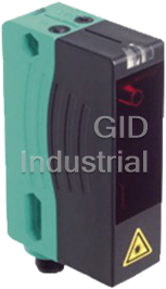
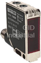
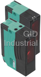
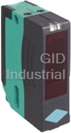
Photoelectric, Laser Distance, DC, IO Link IP65, 8m Sensing, M12 Connector
Universal distance sensor, measurement to object, IO-Link interface, measuring method PRT, 8 m detection range, red laser light, laser class 2, push-pull output, analog output, M12 plug, Distance measurement using object, Measuring method PRT (Pulse Ranging Technology), Accurate, clear, and reproducible measuring results, Minimal black-white difference, Red laser as the light emitter.
Part Number
218499
Price
Request Quote
Manufacturer
PEPPERL+FUCHS
Lead Time
Request Quote
Category
Photoelectric Sensors
Specifications
Part Number
218499
Product Series
VDM Series
Type
General Purpose Photoelectric
Sensing Method
Distance Measurement
Size
Rectangular
Connection
Quick Disconnect
NPN or PNP
See Spec or N/A
0)Product Series
No
Ratings
IP67
Weight - lbs.
0.2000
Base Unit of Measure
Each
Categorization Information
Photoelectric Sensors
Photoelectric, Laser Distance, DC, IO Link-218499
Features
- Distance measurement using object
- Measuring method PRT (Pulse Ranging Technology)
- Accurate, clear, and reproducible measuring results
- Minimal black-white difference
- Red laser as the light emitter
- Version with IO-Link interface
- Version with analog output
- Version with laser class 2
Datasheet

Extracted Text
Distance measurement sensor with IO-Link interface VDM28-8-L-IO/73c/110/122 Dimensions 54.3 14.8 25.8 8 23.8 ø 5.2 9.8 10 M12 54.6 Model Number VDM28-8-L-IO/73c/110/122 Electrical connection Distance sensor with 4-pin, M12 x 1 connector Option: 1 +UB Features Distance measurement using object analog 2 Q2 Measuring method PRT (Pulse Ran- ging Technology) Accurate, clear, and reproducible 3 0 V measuring results Minimal black-white difference 4 C/Q1 Red laser as the light emitter Version with IO-Link interface = Light on Version with analog output = Dark on Version with laser class 2 Pinout Product information The VDM28 distance measurement device 1 employs Pulse Ranging Technology (PRT). It has a repeat accuracy of 5 mm with an ope- 2 4 rating range of 0.2...8m and an absolute accuracy of 25 mm. The compact housing of the Series 28 photo- 3 electric sensors, with dimensions of 88 mm (height), 26 mm (width) and 54 mm (depth), make it the smallest device available in its class. Indicators/operating means 5 2 3 2 1 Operating display green 2 Signal display yellow SET 3 TEACH-IN button A Q1 B RUN A 4 Mode rotary switch Q2 B 5 Laser output 1 4 Refer to “General Notes Relating to Pepperl+Fuchs Product Information”. Pepperl+Fuchs Group USA: +1 330 486 0001 Germany: +49 621 776 4411 Singapore: +65 6779 9091 1 www.pepperl-fuchs.com fa-info@us.pepperl-fuchs.com fa-info@de.pepperl-fuchs.com fa-info@sg.pepperl-fuchs.com Release date: 2015-02-26 14:42 Date of issue: 2015-02-26 218499_eng.xml 54.9 7 2 18 9 12 93 62 11 6 88 102 Distance measurement sensor with IO-Link interface VDM28-8-L-IO/73c/110/122 Technical data Laserlabel General specifications Measurement range 0.2 ... 8 m LASER LIGHT Reference target Kodak white (90%) DO NOT STARE INTO BEAM Light source laser diode CLASS 2 LASER PRODUCT WAVELENGTH: 660 nm typ. service life 85,000 h at Ta = +25 °C MAX PULSE ENERGY: < 4 nJ PULSE DURATION: 5 ns Light type modulated visible red light IEC 60825-1: 2007 CERTIFIED. Laser nominal ratings COMPLIES WITH 21 CFR 1040.10 AND 1040.11 EXCEPT FOR DEVIA- Note LASER LIGHT , DO NOT STARE INTO BEAM TIONS PURSUANT TO LASER NOTICE NO. 50, DATED JUNE 24, 2007. Laser class 2 Wave length 660 nm Beam divergence 1 mrad Pulse length 5 ns LUMIÈRE LASER NE PAS REGARDER LE FAISCEAU Repetition rate 250 kHz PRODUIT LASER CLASSE 2 LONGUEUR D’ONDE: 660 nm max. pulse energy < 4 nJ MAX. ÉNERGIE D’IMPULSION: < 4 nJ DURÉE D’IMPULSION: 5 ns Angle deviation max. ± 2° CERTIFIÉ CEI 60825-1: 2007. CONFORME AUX NORMES 21 CFR Measuring method Pulse Ranging Technology (PRT) 1040.10 ET 1040.11 À L’EXCEPTION DES ÉCARTS CONFORMÉMENT Diameter of the light spot < 10 mm at a distance of 8 m at 20 °C À LA NOTICE DU LASER N° 50, DATÉE DU 24 JUIN 2007. Ambient light limit 50000 Lux Temperature influence typ. ≤ 0.25 mm/K Functional safety related parameters MTTF 200 a d Accessories Mission Time (T) 10 a M PACTware 4.X Diagnostic Coverage (DC) 0 % FDT Framework Indicators/operating means Operation indicator LED green VDM28 IODD Function indicator 2 LEDs yellow for switching state IODD for communication with VDM28-IO- Teach-In indicator Teach-In: LED green/yellow equiphase flashing; 2.5 Hz Link sensors Teach Error:LED green/yellow non equiphase flashing; 8.0 Hz Control elements 5-step rotary switch for operating modes selection (threshold VDM28-IO-Link DTM setting and operating modes) Device DTM for communication with Control elements Switch for setting the threshold values VDM28-IO-Link sensors Electrical specifications Operating voltage U 10 ... 30 V DC / when operating in IO-Link mode: 18 ... 30 V B IO-Link-Master02-USB Ripple 10 % within the supply tolerance IO-Link master, supply via USB port or se- No-load supply current I ≤ 70 mA / 24 V DC 0 parate power supply, LED indicators, M12 Time delay before availability t 1.5 s v plug for sensor connection Interface Interface type IO-Link IO-Link-Master-USB DTM Protocol IO-Link V1.0 Communication DTM for use of IO-Link- Cycle time min. 2.3 ms Master Mode COM 2 (38.4 kBaud) Process data witdh 16 bit IODD Interpreter DTM SIO mode support yes Software for the integration of IODDs in a Output frame application (e. g. PACTware) Signal output Push-pull output, short-circuit protected, reverse polarity protec- ted IO-Link-Master01-USB Switching voltage max. 30 V DC IO-Link master, supply via USB port or se- Switching current max. 100 mA parate power supply, LED indicators, M12 Measurement output 1 analog output 4 ... 20 mA, short-circuit/overload protected plug for sensor connection Switching frequency f 50 Hz Response time 10 ms OMH-05 Measurement accuracy Mounting aid for round steel ø 12 mm or Absolute accuracy ± 25 mm sheet 1.5 mm ... 3 mm Repeat accuracy < 5 mm Ambient conditions OMH-22 Ambient temperature -30 ... 50 °C (-22 ... 122 °F) Mounting bracket Storage temperature -30 ... 70 °C (-22 ... 158 °F) OMH-21 Mechanical specifications Mounting bracket Degree of protection IP65 Connection 4-pin, M12 x 1 connector OMH-07 Material Mounting aid for round steel ø 12 mm or Housing Plastic ABS sheet 1.5 mm ... 3 mm Optical face Plastic pane Mass 90 g OMH-MLV11-K Compliance with standards and directi- dove tail mounting clamp ves Directive conformity EMC Directive 2004/108/EC OMH-RLK29-HW Standard conformity Mounting bracket for rear wall mounting Product standard EN 60947-5-2:2007 IEC 60947-5-2:2007 OMH-RL28-C Laser class IEC 60825-1:2007 Complies with 21 CFR 1040.10 and 1040.11 Weld slag cover model except for deviations pursuant to Laser Notice No. 50, dated June 24, 2007 OMH-K01 dove tail mounting clamp Approvals and certificates Refer to “General Notes Relating to Pepperl+Fuchs Product Information”. Pepperl+Fuchs Group USA: +1 330 486 0001 Germany: +49 621 776 4411 Singapore: +65 6779 9091 2 www.pepperl-fuchs.com fa-info@us.pepperl-fuchs.com fa-info@de.pepperl-fuchs.com fa-info@sg.pepperl-fuchs.com Release date: 2015-02-26 14:42 Date of issue: 2015-02-26 218499_eng.xml Distance measurement sensor with IO-Link interface VDM28-8-L-IO/73c/110/122 Protection class II, rated voltage ≤ 250 V AC with pollution degree 1-2 accor- ding to IEC 60664-1 UL approval cULus Listed, Class 2 Power Source, Type 1 enclosure CCC approval CCC approval / marking not required for products rated ≤36 V Curves/Diagrams Measuring range Object colour black 10 % grey 18 % white 90 % 01 2 3 4 5 6 78 Distance [m] Preferences Teach-In: You can use the rotary switch to select the relevant switching threshold A and/or B for teaching in for switching output Q1. The yellow LEDs indicate the current state of the selected output. To store a switching threshold (distance measured value), press and hold the "SET" button until the yellow and green LEDs flash in phase (approx. 2 s). Teach-In starts when the "SET" button is released. Successful Teach-In is indicated by alternating flashing (2.5 Hz) of the yellow and green LEDs. An unsuccessful Teach-In is indicated by rapidly alternating flashing (8 Hz) of the yellow and green LEDs. After an unsuccessful Teach-In, the sensor continues to operate with the previous valid setting after the relevant visual fault signal is issued. Different switching modes can be defined by teaching in the relevant distance measured values for the switching thresholds A and B: A leer B leer B A A > B B > A BA AB Every taught-in switching threshold can be retaught (overwritten) by pressing the SET button again. Pressing and holding the "SET" button for > 5 s completely deletes the taught-in value. The yellow and green LEDs go out simultaneously to indi- cate that this procedure has been completed. Minimum and maximum values for the analog output Q2 are taught in in the same way as those for the switching output: The following values apply: A = 4 mA B = 20 mA This provides three different options for operation: A < B -> rising slope A > B -> falling slope 20 20 4 4 AB BA Refer to “General Notes Relating to Pepperl+Fuchs Product Information”. Pepperl+Fuchs Group USA: +1 330 486 0001 Germany: +49 621 776 4411 Singapore: +65 6779 9091 3 www.pepperl-fuchs.com fa-info@us.pepperl-fuchs.com fa-info@de.pepperl-fuchs.com fa-info@sg.pepperl-fuchs.com Release date: 2015-02-26 14:42 Date of issue: 2015-02-26 218499_eng.xml Distance measurement sensor with IO-Link interface VDM28-8-L-IO/73c/110/122 A empty -> zero start point 20 4 B Reset to default settings: Factory setting for switching output Q1: Switching output inactive Factory setting for analog output Q2: A = 200 mm B = 5000 mm Value B cannot be deleted The "zero start point" operating mode can be obtained by deleting value A Set the rotary switch to the "RUN" position Press and hold the "SET" button until the yellow and green LEDs stop flashing in phase (approx. 10 s) When the green LED lights up continuously, the procedure is complete. Error messages: Short circuit: In the event of a short circuit at the sensor output, the green LED flashes with a frequency of approx. 4 Hz. Teach error:In the event of a teach error, the yellow and green LEDs flash alternately with a frequency of approx. 8 Hz. Note! The difference in the taught-in distance measured values for switching thresholds A and B must be greater than 20 mm. If the difference in the taught-in measured values is the same as or smaller than the set switching hysteresis, the sensor will visually signal an unsuccessful Teach-In. The last distance measured value that was taught in will not be adopted by the sensor. Select a new distance measured value for switching threshold A or B with a greater difference between the switching thresholds. Teach in this distance measured value on the sensor again. Switching threshold A can be deleted or set to a value of zero. (E.g., when setting the "zero start point" curve). However, switching threshold B can neither be deleted nor set to a value of zero. Laser notice laser class 2 The irradiation can lead to irritation especially in a dark environment. Do not point at people! Caution: Do not look into the beam! Maintenance and repairs should only be carried out by authorized service personnel! Attach the device so that the warning is clearly visible and readable. Caution Use of controls or adjustments or performance of procedures other than those specified herein may result in hazardous radiation exposure. Refer to “General Notes Relating to Pepperl+Fuchs Product Information”. Pepperl+Fuchs Group USA: +1 330 486 0001 Germany: +49 621 776 4411 Singapore: +65 6779 9091 4 www.pepperl-fuchs.com fa-info@us.pepperl-fuchs.com fa-info@de.pepperl-fuchs.com fa-info@sg.pepperl-fuchs.com Release date: 2015-02-26 14:42 Date of issue: 2015-02-26 218499_eng.xml
Frequently asked questions
Why choose IPC Station?

What is IPC Station' warranty policy for the 218499?
What carriers does IPC Station use to ship parts?
Does IPC Station sell to international (non-USA) customers?
What methods of payment does IPC Station accept?
Why buy from GID?

Quality
We are industry veterans who take pride in our work

Protection
Avoid the dangers of risky trading in the gray market

Access
Our network of suppliers is ready and at your disposal

Savings
Maintain legacy systems to prevent costly downtime

Speed
Time is of the essence, and we are respectful of yours
Related Products
Photoelectric, Light On/Dark On, Background, M12 Plug/Q.D., IP67, 20 to 250mm Adjustable Triangulati...
Photoelectric, Light On/Dark On, Retroreflective, M12 Plug, IP67, 0 to 15m Adjustable Laser retroref...
Photoelectric, Thru-beam, Emitter, IP67 Use with LK28-Z-F1/31/116, Light On/Dark On Thru-beam sensor...
Photoelectric, Thru-beam, Receiver, IP67 Use with LA27-F1/116, 0 to 65m, IP67 Thru-beam sensor, Univ...
Photoelectric, Light On/Dark On, Retroreflective, Polarized, IP67, 0-17m Retroreflective sensor with...
Photoelectric, Mini, Background Suppression, 10... 60 mm Range, M8 Connector, 4-pin Triangulation se...
Request a Quote

The quote request has been received
Close

Facing challenges or have inquiries? Feel free to contact us!
Call Us +1-469-283-2440
What they say about us
FANTASTIC RESOURCE
One of our top priorities is maintaining our business with precision, and we are constantly looking for affiliates that can help us achieve our goal. With the aid of GID Industrial, our obsolete product management has never been more efficient. They have been a great resource to our company, and have quickly become a go-to supplier on our list!
Bucher Emhart Glass
EXCELLENT SERVICE
With our strict fundamentals and high expectations, we were surprised when we came across GID Industrial and their competitive pricing. When we approached them with our issue, they were incredibly confident in being able to provide us with a seamless solution at the best price for us. GID Industrial quickly understood our needs and provided us with excellent service, as well as fully tested product to ensure what we received would be the right fit for our company.
Fuji
HARD TO FIND A BETTER PROVIDER
Our company provides services to aid in the manufacture of technological products, such as semiconductors and flat panel displays, and often searching for distributors of obsolete product we require can waste time and money. Finding GID Industrial proved to be a great asset to our company, with cost effective solutions and superior knowledge on all of their materials, it’d be hard to find a better provider of obsolete or hard to find products.
Applied Materials
CONSISTENTLY DELIVERS QUALITY SOLUTIONS
Over the years, the equipment used in our company becomes discontinued, but they’re still of great use to us and our customers. Once these products are no longer available through the manufacturer, finding a reliable, quick supplier is a necessity, and luckily for us, GID Industrial has provided the most trustworthy, quality solutions to our obsolete component needs.
Nidec Vamco
TERRIFIC RESOURCE
This company has been a terrific help to us (I work for Trican Well Service) in sourcing the Micron Ram Memory we needed for our Siemens computers. Great service! And great pricing! I know when the product is shipping and when it will arrive, all the way through the ordering process.
Trican Well Service
GO TO SOURCE
When I can't find an obsolete part, I first call GID and they'll come up with my parts every time. Great customer service and follow up as well. Scott emails me from time to time to touch base and see if we're having trouble finding something.....which is often with our 25 yr old equipment.
ConAgra Foods